32.3.1.3. Constraint Bearing
A Constraint bearing is defined between two bodies. The created position types are five:
Engine Block & Shaft Main (EB_SM)
Shaft Pin & Connecting Rod (SP_CR)
Connecting Rod & Piston Pin (CR_PP)
Piston Pin & PisTon (PP_PT)
Engine Block & Balancing Shaft (EB_BS)
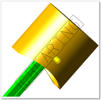
Figure 32.123 Constraint bearing
32.3.1.3.1. Modeling Options
Click the Constraint icon of the Crank Connector group in the Crank tab. The user can see the Crank Component Bearing – Constraint Bearing dialog box.
The user can choose the following types in Component Type and select the position where the constraint bearing is created in Component Index.
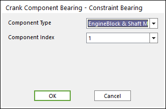
Figure 32.124 Crank Component Bearing – Constraint Bearing dialog box
Click OK
32.3.1.3.2. Properties
Click the right mouse button on the constraint bearing component to choose Properties of constraint bearing. The user can modify the property of a constraint bearing in following dialog box.
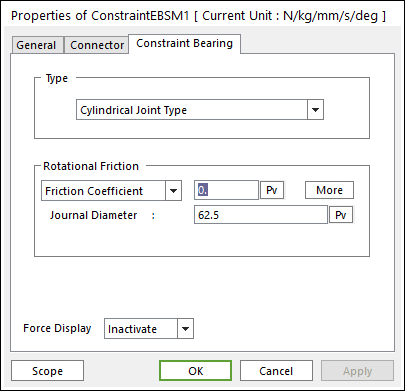
Figure 32.125 Constraint Bearing property page
Type: Spherical Joint, Cylindrical Joint and Revolute Joint Type.
The user can refer the following table for each constraint bearing.
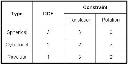
Table 1 Constraint bearing characteristics
Please refer to the Friction types in below.
Standard Friction
Select Friction Coefficient in the combo box
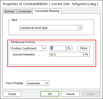
Figure 32.126 Coulomb Friction
Journal Radius: shaft radius attached bearing inside
Click More and enter the values to define Coulomb Friction
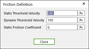
Figure 32.127 Friction Definition dialog box
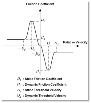
Figure 32.128 Standard Friction
Empirical Formula
Select Empirical Formula in the combo box.
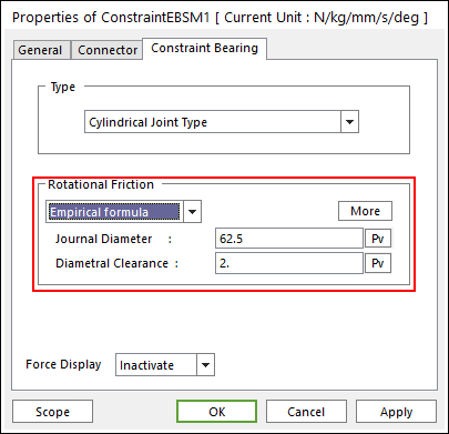
Figure 32.129 Empirical formula Friction
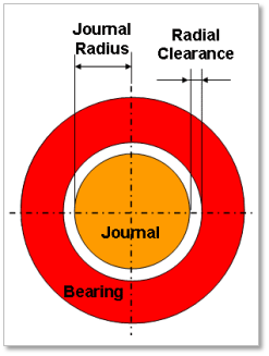
Figure 32.130 Journal Radius & Radial Clearance
Click More and enter the values to define Empirical formula friction
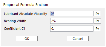
Figure 32.131 Empirical Formula Friction dialog box
Friction Torque
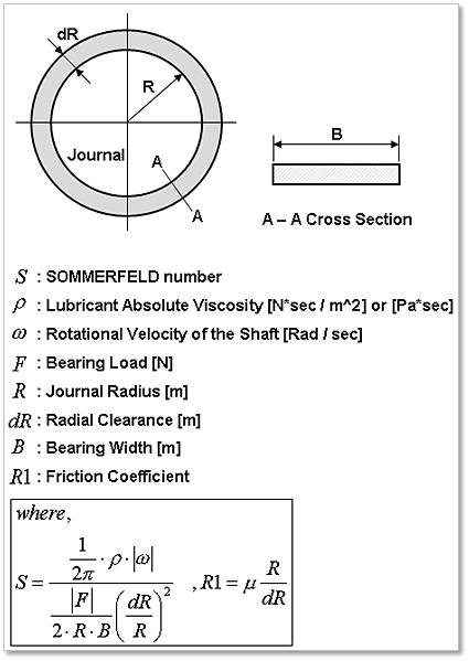
Figure 32.132 Parameters for SOMMERFELD number
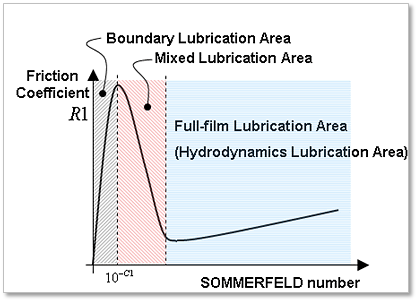
Figure 32.133 Each Lubrication region is decided by SOMMERFELD number
\(\text{Friction Torque}:T=\sum {_i} \eta_i F_i R_i\)
Friction Force
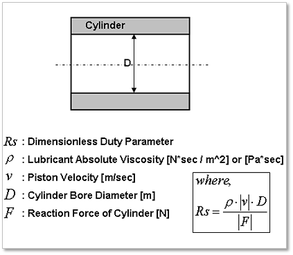
Figure 32.134 Parameters for Dimensionless Duty Parameter
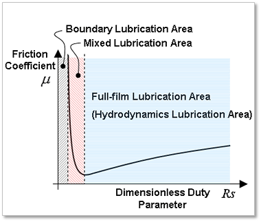
Figure 32.135 Each Lubrication region is decided by Dimensionless Duty Parameter
\(\text{Friction Force}:F=\sum {_i} \eta_i F_i\)
Position information of Constrain Bearing
Engine Block & Shaft Main (EB-SM)
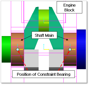
Figure 32.136 Position information of Constraint Bearing between Engine Block & Shaft Main
Shaft Pin & Connecting Rod (SP-CR)
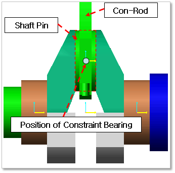
Figure 32.137 Position information of Constraint Bearing between Shaft Pin & Connecting Rod
Connecting Rod & Piston Pin (CR-PP)
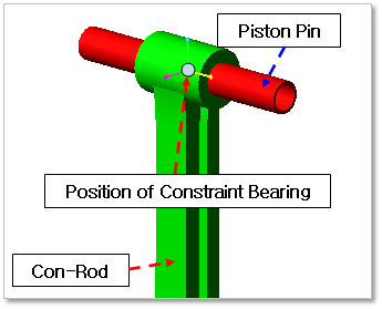
Figure 32.138 Position information of Constraint Bearing between Connecting Rod & Piston Pin
Piston Pin & Piston (PP-PT)
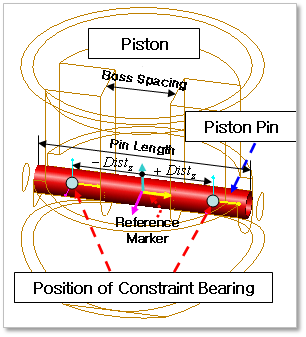
Figure 32.139 Position information of Constraint Bearing between Piston Pin & Piston
The position of Constraint Bearing is decided by following formulation
\(\pm Dist_z=\frac{BossSpacing}{2}+\frac{PinLength-BossSpacing}{4}\)
Engine Block & Balancing Shaft (EB-BS)
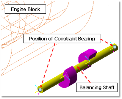
Figure 32.140 Position information of Constraint Bearing between Engine Block & Balancing Shaft