6.4.3.11. Sphere To Arc Revolution
A Sphere To Arc-Revolution Contact generates a force between a sphere and an arc-revolution as a cut sphere.
The sphere and arc-revolution must belong to two different bodies.
The sphere must be defined as action geometry and the arc-revolution must be defined as a base geometry.
The contact force can be generated with not only linear or exponential but also nonlinear spline characteristics to the contact penetration and its velocity.
6.4.3.11.1. Modeling Options
In the case of Sphere To Arc Revolution contact, a sphere geometry type is supported for an action geometry and an arc-revolution surface geometry type for a base geometry when creating. The arc-revolution surface only can be created in RecurDyn. For it, refer to Creating and Editing a Surface from an Arc Geometric Entity.
Surface, Sphere
Surface: Selects a surface to define a base surface.
Sphere: Selects a sphere to define an action sphere.
Surface, MultiSphere
Surface: Selects a surface to define a base surface.
MultiSphere: Selects some spheres to define action spheres.
Surface, Sphere, Surface, Sphere
Surface: Selects a surface to define a base surface.
Sphere: Selects a sphere to define an action sphere.
Surface: Selects a surface to define another base surface.
Sphere: Selects a sphere to define another action sphere.
MultiSurface, MultiSphere
MultiSurface: Selects some surfaces to define action surfaces.
MultiSphere: Selects some spheres to define action spheres.
6.4.3.11.2. Properties
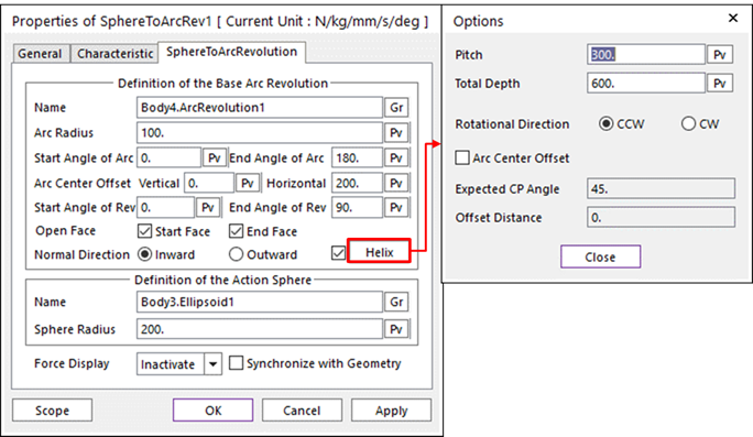
Figure 6.368 Properties of SphereToArcRev dialog box
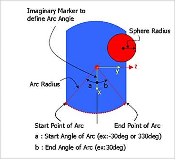
Figure 6.369 Cutting plane according to the direction axis
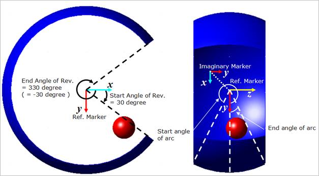
Figure 6.370 Definitions of Start Angle of Rev. and End Angle of Rev.
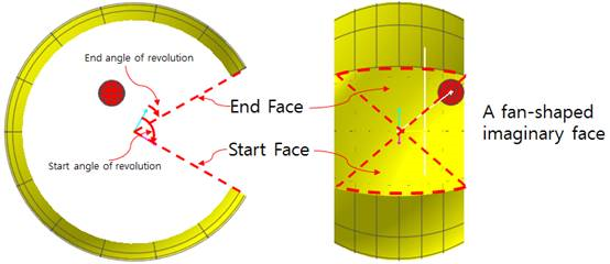
Figure 6.371 Definitions of Start Face and End Face
Definition of The Base Arc Revolution
Entity Name: Defines the name of a base body. The base body can be changed by clicking Gr in the Working Window.
Arc Radius /Start Angle of Arc & End Angle of Arc/ Vertical Offset of Arc Center/ Horizontal Offset of Arc Center/ Start Angle of Rev. & End Angle of Rev.: Shows the information of each parameter. If you modify the information of parameters, you should modify them in the Arc Revolution dialog box or modify them after unchecking the Synchronize with Geometry option in this dialog box.
Normal Direction: Check the contact surface for Inward or Outward.
Open Face: Checks Start Face or (and) End Face. The user can open both side walls respectively. The default is a checked. If the revolution is whole 360D, then the Start Face and End Face contact case is skipped always. The Start Face and End Face is a fan shaped and imaginary wall. The faces located start and end revolution angle respectively.
Helix: The center curve of the arc center is defined on a Helix Curve. For more information, click here.
Pitch: Defines the pitch length of the helix center curve.
Total Depth: Defines the total depth of the helix center curve.
Arc Center Offset: If this check box is checked, the Expected CP Angle and Offset Distance can be applied.
Expected CP Angle (Degree): Defines a negative direction of center offset. The angle means that definitions of expected CP (Contact Point).
Offset Distance: Defines a offset length in order to define a center point of real arc-curve.
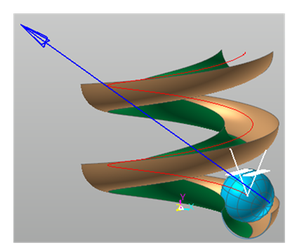
Figure 6.372 Contact between Sphere and a Helix-Torus surface
Definition of The Action Sphere
Entity Name: Defines the name of action body.
Radius: Shows the radius of action sphere.
Synchronize with Geometry
If this option is checked, information regarding the geometry in contact properties is automatically defined with that of the specified graphics. (The default is checked.)
If this option is not checked, the user can modify the contact properties.
Force Display: Graphically displays the resultant force vector on the view window.