12.3.5. AutoMesh
This is a default mesh function in RecurDyn. You can mesh a geometry easily.
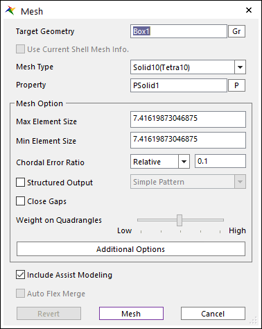
Figure 12.20 Mesh dialog box
Target Geometry: Selects the geometry which performs the mesh function.
Use Current Shell Mesh Info.: After meshing the geometry with shell type, this option is enabled. If this option is checked, solid mesh is created with current shell mesh information. If it’s not, solid mesh is created with the geometry information.
Mesh Type: Selects the element type when you perform the mesh function. RecurDyn/Mesher supports 6 element types as follows.
Shell – Shell3 (Tria3), Shell4 (Quad4)
Note
Shell4 (Quad4) is not pure Quad. But, Quad4 dominant (Tri3 – Quad4 mixed)
Solid – Solid4 (Tetra4), Solid10 (Tetra10), Solid8 (Hexa8)
Note
Solid8 (Hexa8) mesh uses a hex-dominant mesh generator: it builds meshes of 8-node hexahedrons (dominant in volume) and typically 6-node wedges, 5-node pyramids and 4-node tetrahedrons in a conformal manner. There is no quad-triangle junction inside the mesh: two joined elements exactly share every boundary of the elements (except the outer boundaries that belong to only one element).
Property: Selects the applied property to the selected element type.
When you enter the Mesh mode at first, Property types of Beam, Shell and Solid are created automatically. So, you can select Property right away without creating Property.
The default properties have a material defined as the general Steel of isotropic materials. So, if you want to define the material as physical model, you have to change the properties by clicking Data in the Material dialog box.
Mesh Option: Defines the length of created element when the mesher performs the auto- mesh function. The default value is internally defined. But, the use after modifying the value by the user is recommended as following explanations.
Max Element Size: You can set the maximum size of elements. This value is the maximum length of a side to the element. It does not control the defined value absolutely and perfectly. It is used in rough parts to a geometry entity. The default value is 2.5% of diagonal length of Bounding Box to the geometric entity.
Min Element Size: You can set the minimum size of elements. This value is the minimum length of a side to the element. It does not control the defined value absolutely and perfectly. It is used in fine parts which are difficult to mesh using maximum size in a geometry entity.
Chordal Error Ratio: You can set the maximum chordal error. The mesh size is reduced locally to limit the chordal error between the mesh and the initial surface. If relative, this value is relative to the local radius. If absolute, this value is absolute. (Default = 0.1)
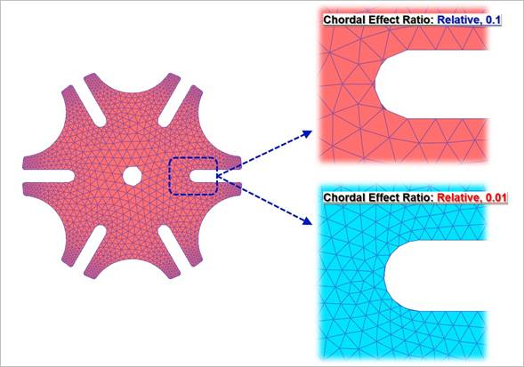
Figure 12.21 Definition for Chordal Effect Ratio
Structured Output: Defines the patterns of created element regularly to improve the quality of mesh when the mesher performs the auto–mesh function. Two patterns are provided as below figures. One is to regularly create the simple pattern to the left direction and the other is to create the Union Jack pattern (the pattern of British flag) which is the type of zigzag.
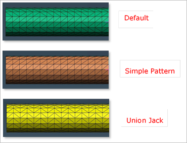
Figure 12.22 Definition for Structured Output
Close Gaps: The tessellation data used in the input of mesh is not certainly guaranteed to perform the topological matching. The below figure shows the example of tessellation data. It can have the invisible gap and it cannot be decided as the solid in the meshed result. So, it makes to wrong the result of mesh terribly or to fail the mesh work. The mesh input is basically guaranteed to do topological matching but the RecurDyn/Mesher can inspect to be the gap and modify it to handle the unsuspected error.
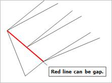
Figure 12.23 Definition for Close Gaps
Weight on Quadrangles: This option can be used only Shell4(Quad4), Solid8(Hexa8) in Mesh Type. This option is about preference for quadrangles versus triangles. If the closer the slider position located at Low, the more triangle patches are made. When slider position exactly located at Low, quadrangles are used only when they improve the quality of the mesh. If the closer the slider located at High, the smaller the number of triangles. When slider position exactly located at High, Forcibly, all element to be generated quad mesh. The Minimize Triangle Element should be preferred to the Quad Element Only, if triangles are accepted. It usually gives better meshes with fewer elements.
Include Assist Modeling: When meshing the target geometry, if there are Constraints and Contacts defined to the target geometry, FDR, Patch Set, and Line Set are created automatically. The information for Constraints and Contacts can be checked on Assist Modeling function.
Auto Flex Merge: When meshing several geometries in consecutive, if they have connected each other, the mesher considers the condition. If there is no mesh, the connected geometries are used to imprint the target geometry. If there is mesh, the mesh shape is used to imprint the target geometry. So, the same shape of the mesh is the result in the connected part. For more information, refer to Step to Create Multi-mesh.
Revert: Returns the geometric entity. It is not possible to exit after reverting in the Mesh mode when entering again after mesh.
Mesh: Executes the mesh. You can see the mesh information such as the number of nodes and elements in Message Window after finishing to mesh geometry.
Cancel: Cancels the mesh and closes the dialog.
Additional Mesh Options
Additional Mesh Options are supported in AutoMesh. Additional Mesh Options provide variety of shell and solid mesh options.
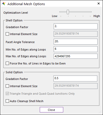
Figure 12.24 Additional Mesh Options dialog box
Optimization Level: When the closer the slider position located at Low, meshing speed is maximal, but the quality may be poor. When slider is located at default position, Optimization is usually a good trade-off between quality and speed. the closer the slider are located at High, the better Element of Shape and size quality.
Shell Option: The below functions support only for Shell element.
Gradation Factor: You can set the gradation factor. The gradation factor adjusts the gradation of the elements size between the Min Element Size towards to the Max Element Size. This value close to 0 leads to a more progressive variation of mesh size. (Shell Default = 2, Solid Default = 0.5)
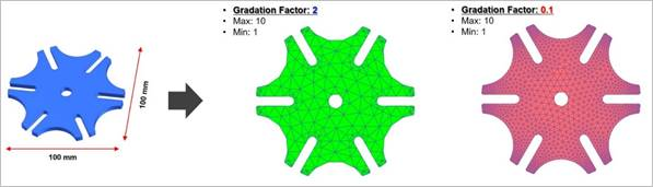
Figure 12.25 Definition for Gradation Factor
Internal Element Size: The elements size tends (according to gradation factor parameter) toward this value as they get away from the edge of patch lines.
Facet Angle Tolerance: If the angle of an adjacent initial facet is greater than the value, it is defined as the edge of the facet. A small value tends to give numerous small facets and the final mesh is close to the initial mesh but may be of poor quality. A big value tends to give fewer bigger facets.
Min/Max No. of Edges along Loops: This parameter defines the minimum/maximum number of edges when meshing holes or loops. This parameter works only for shell mesh.
Force the No. of Lines in Edges to be Even: Flag forces the number of lines in the edge of patch to be even.
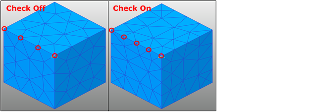
Figure 12.26 Example of Force the No. of Lines in Edges to be Even applied to the mesh
Solid Option: The below functions support only for Solid element.
Internal Element Size: The elements size tends (according to gradation factor parameter) toward this value as they get away from the boundary faces.
Triangle-Triangle and Quad-Quad Junction Only: This flag allows the internal patches to be shared only if the two patches type match exactly. If set to true, only triangle-triangle and quad-quad junctions are allowed. This usually leads to more nodes, more Solid4, 5 (tet, pyramid) and fewer Solid6, 8 (wedge, hex). If set to false, Solid8(hex) for instance can be joined by one of its face to two tetrahedrons (quad – triangle junction).
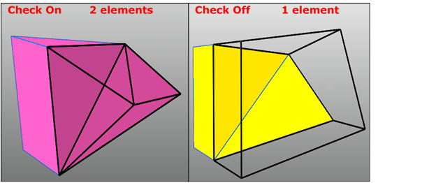
Figure 12.27 Example of Tri-Tri and Quad-Quad Junction Only applied to the mesh
Auto Cleanup Shell Mesh: When the parameter is set to true, if solid mesh fails, the shell mesh is remeshed by modified some options automatically first. Then solid mesh is retried through the modified shell mesh. However, setting to true does not always guarantee the success of the failed case.