41.3.7. Road Data File
The MFTire supports Flat Road, Plank Road, Polyline Road, and Sine Road that are defined in road data file. Simple road data files are provided with the installation. The following lists are parameters of road data file.
RecurDyn provides some files. These files are in the <Install Dir>\Toolkits\MFTire\Road data files.
Flat Road (ROAD_TYPE = ‘flat’)
As the name already indicates this is a flat road surface.
Plank Road (ROAD_TYPE = ‘plank’)
This is a single cleat or plank that is oriented perpendicular, or in oblique direction relative to the X axis with or without bevel edges.
Polyline Road (ROAD_TYPE = ‘poly_line’)
This is the road height as a function of travelled distance.
Sine Road (ROAD_TYPE = ‘sine’)
The road surface consists of one or more sine waves with constant wavelength.
These road surfaces are defined in road data files (*.rdf). Like the tire property file, the road data file consists of various sections indicated with square brackets.
! Comments section
$--------------------------------------------------------------------------UNITS
[UNITS]
LENGTH = 'meter'
FORCE = 'newton'
ANGLE = 'degree'
MASS = 'kg'
TIME = 'sec'
$--------------------------------------------------------------------------MODEL
[MODEL]
ROAD_TYPE = '...'
$---------------------------------------------------------------------PARAMETERS
[PARAMETERS]
...
In the [UNITS] section, the units that are used in the road data file are set.
The [MODEL] section is used to specify the road type, see listing above.
The [PARAMETERS] section contains general parameters and road surface type specific parameters.
The general parameters are listed below:
Parameters |
Descriptions |
MU |
Is the road friction correction factor (not the friction value itself), to be multiplied with the LMU scaling factors of tire model. Default setting: MU = 1.0. |
OFFSET |
Is the vertical offset of ground with respect to inertial frame. This parameter should not be used in GRoad model. Instead, the origin of GRoad is used for road calculation. |
ROTATION_ANGLE_XY_PLANE |
Is the rotation angle of XY-plane about the road Z-axis, i.e. definition of the positive X-axis of road with respect to the inertial frame. |
DRUM_RADIUS |
Is the radius of the drum. |
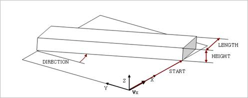
Plank Road
Table 41.12 Plank Road Parameters
Descriptions
HEIGHT
Height of the cleat.
START
Distance along the X-axis of the road to the start of the cleat.
LENGTH
Length of the cleat (excluding bevel) along X-axis of the road.
BEVEL_EDGE_LENGTH
Length of the 45 deg. bevel edge of the cleat.
DIRECTION
Rotation of the cleat about the Z-axis with respect to the Yaxis of the road. If the cleat is placed crosswise, DIRECTION = 0. If the cleat is along the X-axis, DIRECTION = 90.
Polyline
The [PARAMETERS] block must have a (XZ_DATA) subblock. The subblock consists of three columns of numerical data:
Column one is a set of X-values in ascending order.
Columns two and three are sets of respective Z-values for left and right track.
Example:
[PARAMETERS]

MU = 1.0 $ peak friction scaling coefficient

OFFSET = 0 $ vertical offset of the ground wrt inertial frame

ROTATION_ANGLE_XY_PLANE = 0 $ definition of the positive X-axis of the road wrt inertial frame

$

$ X_road Z_left Z_right

(XZ_DATA)

-1.0e04 0 0

0.0500 0 0

0.1000 0 0

0.1500 0 0
Sine Road
The TNO sine road is implemented as:
\[\begin{flalign} z(x) =\frac{H}{2}\left( 1-\cos \left( \frac{2\pi \cdot (X-{{X}_{start}})}{L} \right) \right) && \end{flalign}\]With z: z-coordinate road; H; Height; x: current position; xstart: start of sine wave; L:Length
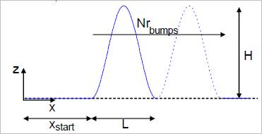
Table 41.13 Sine Road Parameters
Descriptions
HEIGHT
Height of the cleat.
START
Distance along the X-axis of the road to the start of the sine wave
LENGTH
Wavelength of the sine wave along X-axis of the road.
DIRECTION
Rotation of the cleat about the Z-axis with respect to the Yaxis of the road. If the cleat is placed crosswise, DIRECTION = 0. If the cleat is along the X-axis, DIRECTION = 90.
N_BUMPS
Number of consecutive sine bumps.