41.2.2. Slip Ratio & Friction
41.2.2.1. Longitudinal Slip Ratio
The longitudinal slip ratio, \(S\), is defined to be
The absolute value of longitudinal slip ratio, \({{S}_{s}}\), is therefore:
41.2.2.2. Lateral Slip Ratios
The slip angle \(\alpha\) is defined as:
The lateral slip ratio due to slip angle, \({{S}_{\alpha }}\), may then be defined as:
The lateral slip ratio due to inclination angle, \({{S}_{\gamma }}\), is defined as:
A combined lateral slip ratio due to slip and inclination angles, \({{S}_{\alpha \gamma }}\), is defined as:
where, \(\ell \approx \sqrt{8{{r}_{1}}(delta)}\) is the length of the contact patch.
41.2.2.3. Comprehensive Slip Ratio
A comprehensive slip ratio due to slip ratio, slip angle, and inclination angle may be defined as:
Note that:
\({{S}_{s\alpha \gamma }}={{S}_{s}}\) for \(\alpha =\gamma =0\)\({{S}_{s\alpha \gamma }}={{S}_{\alpha }}\) for \(s=\gamma =0\)\({{S}_{s\alpha \gamma }}={{S}_{\gamma }}\) for \(s=\alpha =0\)\({{S}_{s\alpha \gamma }}={{S}_{\alpha \gamma }}\) for \(s=0\)
Now a slip velocity directional angle:math:beta may be defined as:
41.2.2.4. Friction Models in the TIRE Statement
In the Tire statement, a linear relationship between \({{S}_{s\alpha \gamma }}\) and \(\mu\), the corresponding road-tire friction coefficient, is assumed.
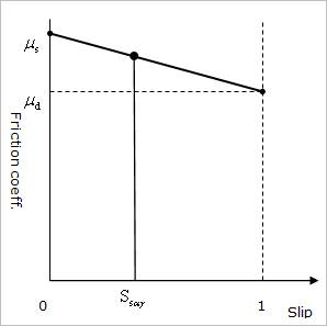
Figure 41.9 Linear Friction Model
The friction circle concept allows for different values of longitudinal and lateral friction coefficients(\({{\mu }_{x}}\) and \({{\mu }_{y}}\)) but limits the maximum value for both coefficients to \(\mu\).
The relationship that defines the friction circle follows:
The Fiala tire model uses only \(\mu\) and not \({{\mu }_{x}}\) and \({{\mu }_{y}}\). The UATIRE model uses \(\mu\), \({{\mu }_{x}}\), and \({{\mu }_{y}}\).