6.1.4.7. Local
In the Local group, the user can perform the detail modeling by using specific functions such as Chamfer, Fillet, and Shell.
6.1.4.7.1. Chamfer
It allows the user to make narrow flat surfaces along the edges of the solid geometric entity. For reference, in the case of applying this function to one edge and all edges of the selected entity, the results can be different because it depends on the complexity of the chamfering operation.
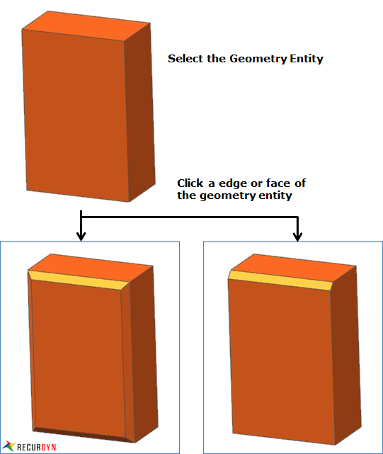
Figure 6.107 Creation of a Chamfer
Modeling Options
The user can work the chamfer operation for one geometric entity by the following procedure.
Solid, WithDialog
Solid: Selects a solid geometry.
WithDialog: Chamfer Operation dialog box appears, and then selects edges. The chamfer operation works by clicking OK in the Chamfer Operation dialog box.
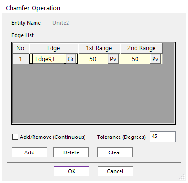
Figure 6.108 Chamfer Operation dialog box [Add an edge]
Entity Name: Shows the name of the selected entity.
Add: Selects edges with chamfer applied. After finishing the operation of selecting multi-edges, the row is added for the selected edges.
Delete: Deletes the selected rows.
Clear: Clears rows.
Edges: Selects edges.
1st Range: Specifies the cutting depth of the selected edge with respect to the first surface.
2nd Range: Specifies the cutting depth of the selected edge with respect to the second surface.
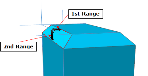
Figure 6.109 1st Range and 2nd Range
Add/Remove (Continuous): When using Add, if this option is checked, the connected faces within the degrees are selected together.
Tolerance (Degrees): The angle between the connected two faces.
6.1.4.7.2. Fillet
It allows the user to create rounded edges and corners. So, the user can regard creating filleted edges as the procedure to round them by rolling a ball over the edges or corners. Additionally, when filleting an edge or corner, the user can specify a start radius and an end radius for the fillet to create a variable fillet. For reference, the user can get different results when applying fillets to one edge at a time and to all edges at once because it depends on the complexity of the filleting.
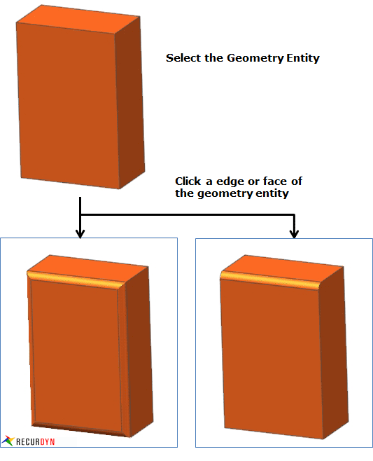
Figure 6.110 Creation of a Fillet
Modeling Options
The user can work the fillet operation for one geometric entity by the following procedure.
Solid, WithDialog
Solid: Selects a solid geometry.
WithDialog: Fillet Operation dialog box appears, and then selects edges. The fillet operation works by clicking OK in the Fillet Operation dialog box.
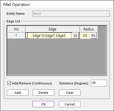
Figure 6.111 Fillet Operation dialog box [Add an edge]
Entity Name: Shows the name of the selected entity.
Add: Selects edges with fillet applied. After finishing the operation of selecting multi-edges, the row is added for the selected edges.
Delete: Deletes the selected rows.
Clear: Clears rows.
Edges: Selects edges.
Radius: Specifies the radius of the selected edge with respect to the first surface.
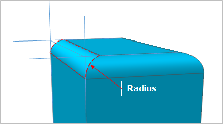
Figure 6.112 Fillet radius
Add/Remove (Continuous): When using Add, if this option is checked, the connected faces within the degrees are selected together.
Tolerance (Degrees): The angle between the connected two faces.
6.1.4.7.3. Shell
It allows the user to modify a solid geometric entity to retain only the shell geometric entity with the user-defined thickness that can be applied to either the interior or exterior boundary of the geometric entity. Additionally, the user can remove the faces of the selected entity.
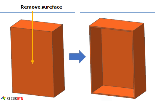
Figure 6.113 Creation of a Shell
Modeling Options
The user can work the shell operation for one geometric entity by the following procedure.
Solid, WithDialog
Solid: Selects a solid geometry.
WithDialog: Shell Operation dialog box appears, and then selects faces. The shell operation works by clicking OK in the Shell Operation dialog box.
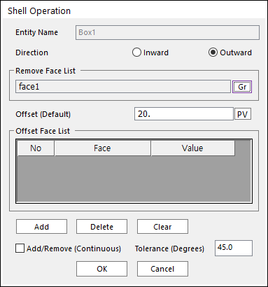
Figure 6.114 Shell Operation dialog box
Entity Name: Shows the name of the selected entity.
Direction: Specifies the direction of the offset as Inward or Outward.
Remove Face List: Shows the list of faces to remove.
Offset (Default): Faces excluding Remove Face List faces are offset with this value.
Offset Face List: Shows the list of faces for the offset. These specify offset values. These faces are offset with their offset values different from the default offset value.
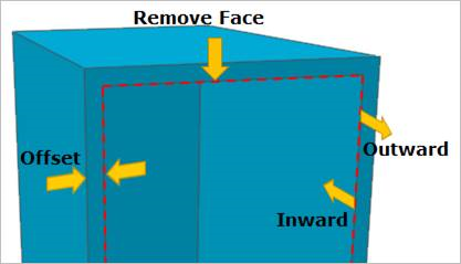
Figure 6.115 Shell Information
Add: Selects faces with shell applied. After finishing the operation of selecting multi-faces, the row is added for the selected faces.
Delete: Deletes the selected row by the mouse cursor and moves the lower rows up.
Clear: Clears rows
Add/Remove (Continuous): When using Add, if this option is checked, the connected faces within the degrees are selected together.
Tolerance (Degrees): The angle between the connected two faces.
6.1.4.7.4. Scale
It allows the user to modify the size of a surface and solid geometries in three directions.
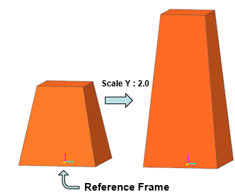
Figure 6.116 Scaling a geometry
Modeling Options
The user can work the scale operation for one geometric entity by the following procedure.
WithDialog
WithDialog: Scale Operation dialog box appears, and then sets the scale. The scale operation works by clicking OK in the Scale Operation dialog box.
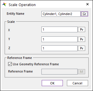
Figure 6.117 Scale operation dialog box
Entity Name: Selects geometries (solid and sheet geometries are available).
Scale X: Defines the ratio value to control the size in the x-direction.
Scale Y: Defines the ratio value to control the size in the y-direction.
Scale Z: Defines the ratio value to control the size in the z-direction.
Use Geometry Reference Frame: When this option is checked, Scale operation is performed based on each geometry reference frame of entities.
Reference Frame: Selects a marker. The size of the geometry changes based on the marker.
6.1.4.7.5. Properties for Hierarchy
The property page shows the local operation hierarchy. In the page, the previous geometries of local operation can be modified in the body edit mode. The properties of previous geometries can be modified.
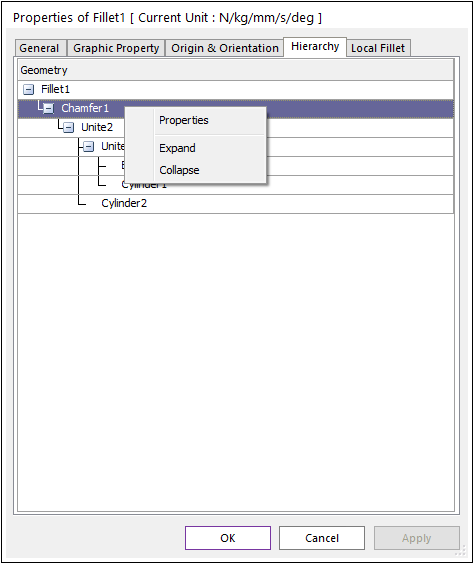
Figure 6.118 Property page of Local [Hierarchy page]
The box is modified with chamfer and fillet operations. After that, the property of the box can be modified in the Hierarchy page of the local geometry.
Context Menu
Properties: Show the properties page of the previous geometry.