9.7.5. Property
There are five property types:
Beam
Shell
Solid
FDR
Mass
Every property has a material type and value that is related to shape.
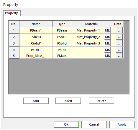
Figure 9.84 Property dialog box
Name: Displays the name of property to the element.
Type: Displays the type of property to the element.
Material: Displays the type of material to the element. You can modify the property of material by clicking Mt..
Data: Defines the data of property to the element type.
Add: Adds a desired property type below the last row of the property list by the Property Type dialog box.
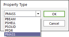
Figure 9.85 Property Type dialog box
Property Type: Selects a type among the following list.
PBEAM
PSHELL
PSOLID
PFDR
PMASS
Insert: Inserts a desired property type below the desired row of the property list by the Property Type dialog box.
Delete: Deletes the desired row the property list.
9.7.5.1. PBeam
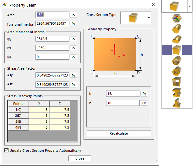
Figure 9.86 Property Beam dialog box
Area [ \(Length^2\) ]: Defines the cross-section area of beam element.
Torsional Inertia [ \(Mass*Length^2\) ]: Defines the moment of inertia on the longitudinal direction.
Iyy [ \(Mass*Length^2\) ]: Defines the moment of inertia on the y direction.
Izz [ \(Mass*Length^2\) ]: Defines the moment of inertia on the z direction.
Iyz [ \(Mass*Length^2\) ]: Defines the moment of inertia on the yz plane.
Asy, Asz: Define shear area factor. This factor is used for considering shear transformation by shear force which cause that neutral axis is not perpendicular to cross-section. This value is 5/6 in the case of rectangle and 0.9 in the case of circle cross-section.
Cross Section Type: Beam cross section type can be selected. RecurDyn supports the circle, ellipse, rectangle, hollow circle, hollow rectangle, I beam and T beam cross sections. The cross section’s geometric characteristics can be defined.
Stress Recovery Points: Defines the y and z locations in element coordinates relative to the beam center line for stress data recovery.
Recalculate: Property values are updated when recalculating.
Update Cross Section Property Automatically: If this option is checked, property values are updated automatically as geometry data change without clicking Recalculate.
The beam library automatically calculates the mass and area moment of inertia which is determined by the cross-section area. Refer to Beam Library.
9.7.5.2. PSHELL
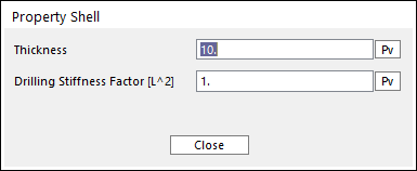
Figure 9.87 Property Shell dialog box
Thickness [ \(Length\) ]: Defines the thickness of shell element. In variable thickness element (shell4), this thickness is not applied. To set the variable thickness, Refer to Shell Element Property Page.
Drilling Stiffness Factor: Defines the multiplier factor of drilling stiffness. If the drilling of shell element is too flexible, then the shell element can be changed stiffer for only drilling stiffness by enlarging the factor.
9.7.5.3. PFDR
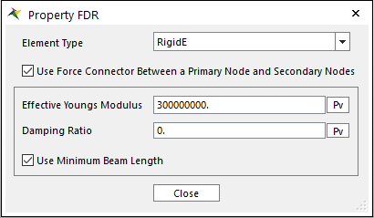
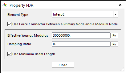
Figure 9.88 Property PFDR dialog box
Element Type: There are two types of FDR property. First one is RigidE and second one is InterpE. RigidE type connects primary node to secondary nodes by rigid element and InterpE type connects primaty node to meadium node by rigid element and the medium node to secondary nodes by interpolation element. For more information about rigid/interpolation element, click here.
Use Force Connector Between a Primary Node and Secondary Nodes: This option is only valid for RigidE type. If this option is checked, the primary node is connected to the secondary nodes by rigid element of force type (= force connector). if not, they are connected by rigid element of constraint type. If Sync. FDR option in the Properties of FFlex body dialog box is checked, this option is defined automatically according to it. For more information, click here.
Use Force Connector Between a Primary Node and Medium Nodes: This option is only valid for InterpE type. If this option is checked, the primary node is connected to the medium node by rigid element of force type (= force connector). if not, they are connected by rigid element of constraint type. If Sync. FDR option in the Properties of FFlex body dialog box is checked, this option is defined automatically according to it. For more information, click here.
Effective Youngs Modulus [ \(Force/Length^2\) ]: Defines the effective Young’s modulus for the force connector. The force connector follows beam element force formula.
Damping Ratio: Defines the damping ratio for the force connector.
Use Minimum Beam Length: If this option is checked, the minimum beam length (= Averaging all connector length *0.1) calculated internally is used for the force connector. The length of force connector which is shorter than the minimum beam length is replaced by the minimum beam length. This is for avoiding that some force connector with very small length causes excessive stiffness force.
Note
According to the interpolation element formula, initially the secondary nodes should be connected to the node at their average position. So, a medium node is automatically generated at average position of secondary nodes in order to meet this requirement. Thus, the primaty node is not connected to secondary nodes directly but connected to medium node by rigid element and the medium node is connected to secondary nodes by interpolation element. So, if InterpE is set, rigid element and interpolation element are set both.
9.7.5.4. PMass
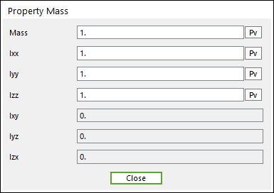
Figure 9.89 Property Mass dialog box
Mass [ \(Mass\) ]: Defines the mass.
Ixx [ \(Mass*Length^2\) ]: Defines the moment of inertia on the x direction.
Iyy [ \(Mass*Length^2\) ]: Defines the moment of inertia on the y direction.
Izz [ \(Mass*Length^2\) ]: Defines the moment of inertia on the z direction.
Ixy [ \(Mass*Length^2\) ]: Defines the moment of inertia on the xy plane.
Iyz [ \(Mass*Length^2\) ]: Defines the moment of inertia on the yz plane.
Izx [ \(Mass*Length^2\) ]: Defines the moment of inertia on the zx plane.