32.2.2. CrankShaft
A crankshaft is group, which is composed of multi bodies as following Figure 32.41.
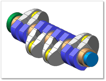
Figure 32.41 CrankShaft
32.2.2.1. Modeling Options
Click the Shaft icon of the Crank group in the Crank tab. The user can see the Crank Component – CrankShaft dialog box.
The position of Crank Shaft is automatically defined.
Only one crankshaft should exist at the current system.
If the crankshaft already exists, the user cannot create crankshaft anymore.
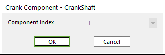
Figure 32.42 Crank Component-CrankShaft dialog box
Click OK.
32.2.2.2. Properties
Click the right mouse button on the crank shaft body to choose Properties of the crank shaft. The user can modify the property of crank shaft in the following dialog.
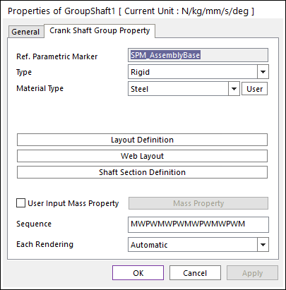
Figure 32.43 Crank Shaft property page
Reference Parametric Marker: Controls the position of crankshaft. It is also special parametric marker (SMP).
Type: Selects the type of crankshaft. It defines the connection method between multi bodies.
Material Type: Specifies the material of crankshaft.
Sequence: Shows current crankshaft’s composition of multi bodies briefly.
‘M’ means shaft main body
‘P’ means shaft pin body
‘W’ means shaft web body
‘w’ means shaft inner web body.
Each Rendering: The selected mode can be displayed in Each Render mode.
32.2.2.2.1. Crank Shaft Type
Rigid Type All multi bodies are connected by fixed joint. It acts like one body.
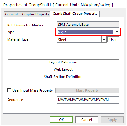
Figure 32.44 Properties of GroupShaft dialog box [Rigid Type]
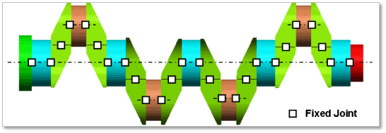
Figure 32.45 Rigid Type of the Crank Shaft
Torsional Type Multi bodies are connected by Fixed Joint and Rotational Spring Damper with Revolute Joint. It acts like flexible body.

Figure 32.46 Properties of GroupShaft dialog box [Torsional Type]
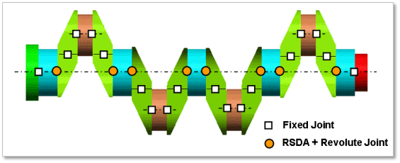
Figure 32.47 Torsional Type of the Crank Shaft
The user can modify the property of rotational spring damper that connects multi bodies. For more information, refer to Rotational Spring Force. If the user clicks RSDA Property, the user can see the following dialog box.
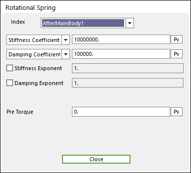
Figure 32.48 Rotational Spring dialog box
Torsional & Bending Type Multi bodies are connected by Fixed Joint and Bushing Force. It acts like flexible body.
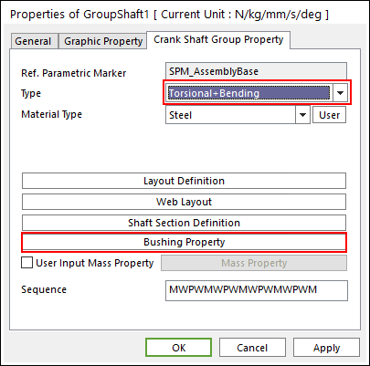
Figure 32.49 Properties of GroupShaft dialog box [Torsional & Bending Type]
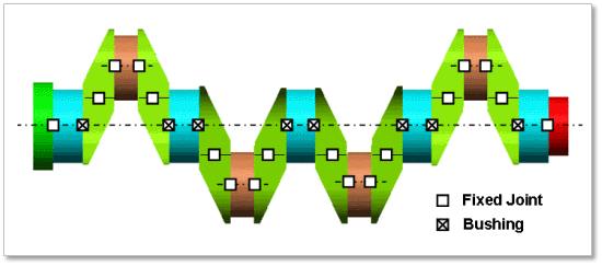
Figure 32.50 Torsional & Bending Type of the Crank Shaft
The user can modify the property of bushing force that connects multi bodies. For more information, refer to Bushing Force. If the user clicks Bushing Property, the user can see the following dialog box.
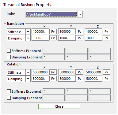
Figure 32.51 Torsional Bushing Property dialog box
Beam Type Multi bodies are connected by Beam Force. It acts like flexible body.

Figure 32.52 Properties of GroupShaft dialog box [Beam Type]
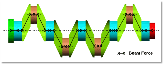
Figure 32.53 Beam Type of the Crank Shaft
The user can modify the property of Beam Force that connects multi bodies. The user has to specify the value of Shear Modulus that is used to calculate Beam Force. For more information, refer to Beam Force. If the user clicks Beam Property, the user can see the following dialog box. There are two types of Beam, such as circle and rectangle type.
32.2.2.2.2. Layout Definition
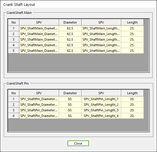
Figure 32.54 Crank Shaft Layout dialog box
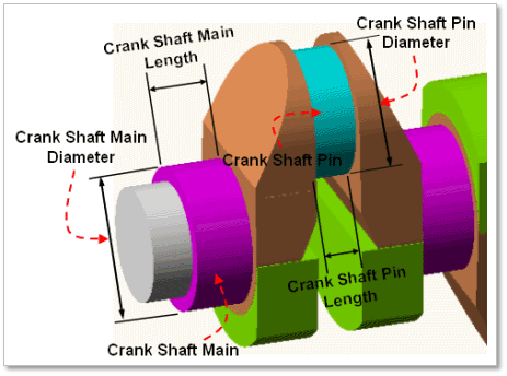
Figure 32.55 Geometrical information of Crank Shaft Layout
32.2.2.2.3. Web Layout
In Web Layout Dialog, the user can modify the geometrical information of the web and the counter weight of web in crankshaft. The position of web is automatically calculated by the related bodies, main and pin of crankshaft. But the shape of web can be changed in this dialog by the parameter of Primary Edge Height, Secondary Edge Height, Primary Edge Length and Secondary Edge Length. For counter weight, the user can modify the position and orientation by changing the parameter of Pos(A) / Angle of CG and can also modify the shape by the parameter of Radius of CG.
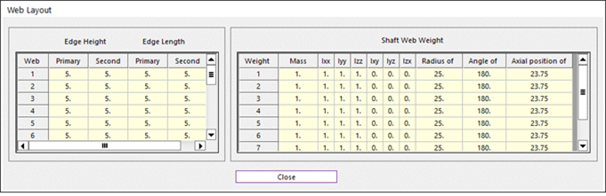
Figure 32.56 Web Layout dialog box
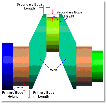
Figure 32.57 Geometrical information about Web
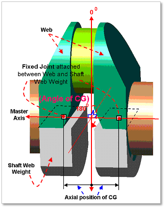
Figure 32.58 Geometrical information about Web Weight
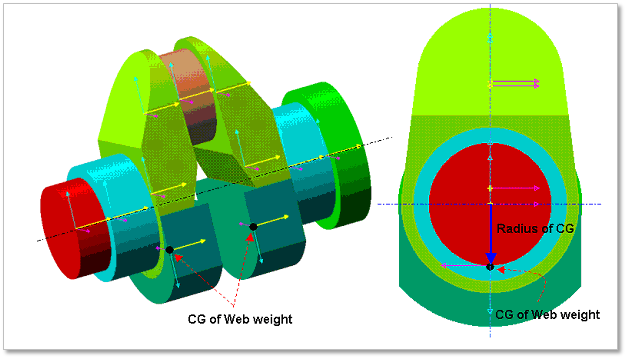
Figure 32.59 Geometrical information about Shaft Web Weight
32.2.2.2.4. Shaft Section Definition
In Shaft Section Definition dialog, the user can modify the geometrical information of the section body located at both end of crankshaft. For now, the number of section body at front end of crankshaft and at rear end of crankshaft is fixed as one respectively. The Length and Diameter of each body can be modified in this dialog.
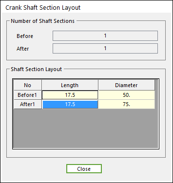
Figure 32.60 Crank Shaft Section Layout dialog box
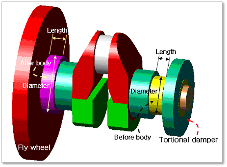
Figure 32.61 Geometrical information of Crank Shaft Section Layout