34.2.2. Rocker Arm
The user can create Rocker Arm as 4 types.
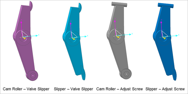
Figure 34.85 RockerArm
34.2.2.1. Properties
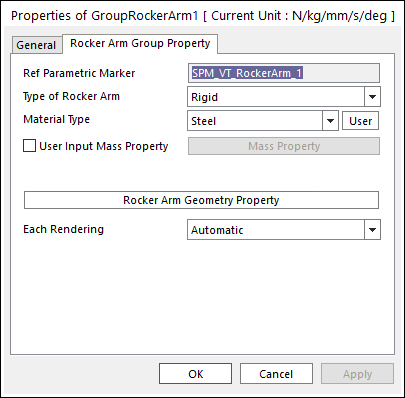
Figure 34.86 GroupRockerArm property page
Ref Parametric Marker: Controls the position of Rocker Arm. It is also special parametric marker (SPM).
Type of Rocker Arm: Selects the type of Rocker Arm. It defines the connection method between multi bodies.
Material Type: Selects a material type. Three method are supported. For more information, click here.
Rocker Arm Geometry Property: Defines some geometry data and property data for Rocker Arm. Cam Roller and Slipper types are supported and the type can be selected in Valve Global Data dialog box.
Each Rendering: The selected mode can be displayed in Each Render mode.
34.2.2.1.1. Type of Rocker Arm
Rigid Type
All multi bodies are connected by fixed joint. It acts like one body.
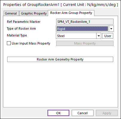
Figure 34.87 Rocker Arm property page [Rigid Type]
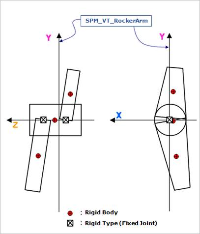
Figure 34.88 Rigid Type of the Rocker Arm
Torsional & Bending Type
Multi bodies are connected by Bushing Force. It acts like flexible body.

Figure 34.89 Rocker Arm property page [Torsional & Bending Type]
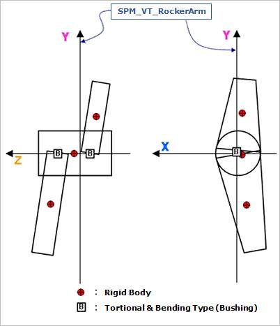
Figure 34.90 Torsional & Bending Type of the Rocker Arm
Bushing Property: If Torsional & Bending type of Rocker Arm is selected, this function is activated and defines bushing property data. For more information, refer to Bushing Force.
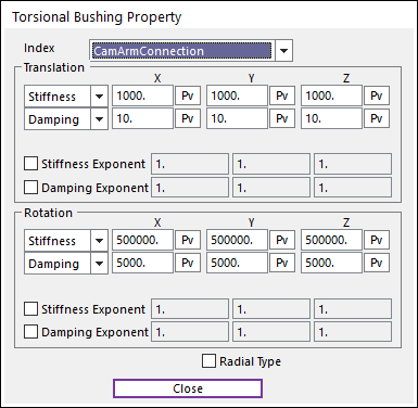
Figure 34.91 Torsional Bushing Property dialog box
Beam Type
Multi bodies are connected by Beam Force. It acts like flexible body.
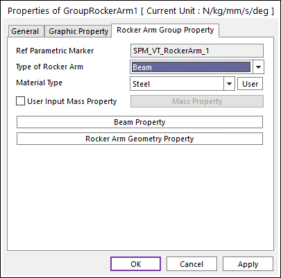
Figure 34.92 Rocker Arm property page [Beam Type]
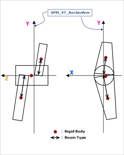
Figure 34.93 Beam Type of the Rocker Arm
Beam Property: If Beam type of Rocker Arm is selected, this function is activated and defines beam force property data. For more information, refer to Beam Force.
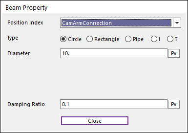
Figure 34.94 Beam Property dialog box
34.2.2.1.2. Rocker Arm Geometry Property
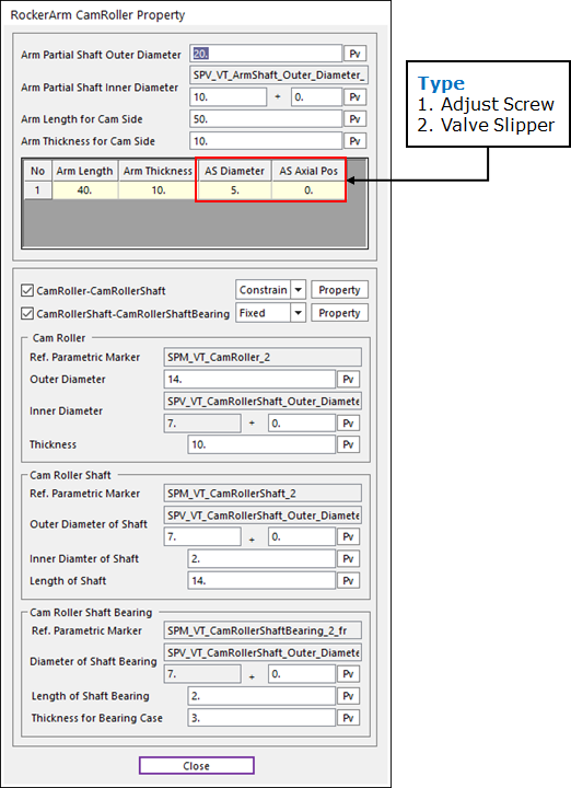
Figure 34.95 RockerArm CamRoller Property dialog box [CamRoller – AdjustScrew Type]
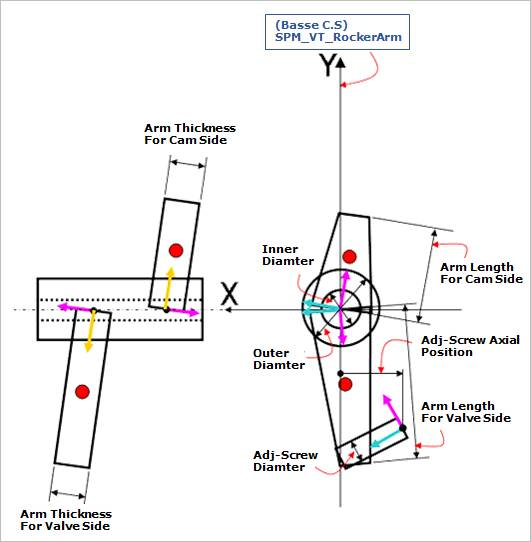
Figure 34.96 Geometric information
Arm Partial Shaft Outer Diameter: Defines an outer diameter of Arm Partial Shaft.
Arm Partial Shaft Inner Diameter: Defines an inner diameter of Arm Partial Shaft.
Arm Length for Cam Side: Defines a length of arm for Cam Side.
Arm Thickness of Cam Side: Defines a thickness of arm for Cam Side.
Arm Length: Defines a length of arm for Valve Side.
Arm Thickness: Defines a thickness of arm for Valve Side.
AS Diameter: Defines a diameter of Adjust Screw.
AS Axial Pos: Defines an axial position of Adjust Screw.
VS Length: Defines a length of Valve Slipper.
VS Width: Defines a width of Valve Slipper.
34.2.2.1.2.1. CamRoller Type
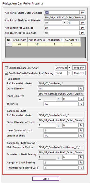
Figure 34.97 RockerArm CamRoller Property dialog box
CamRoller – CamRollerShaft
Constraint Bearing
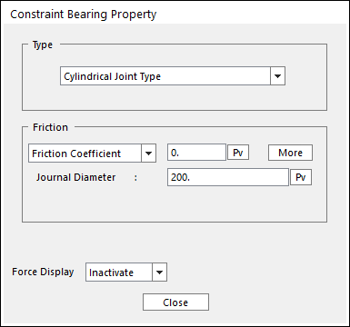
Figure 34.98 Connection of CamRoller - CamRollerShaft
Type
Spherical Joint Type: For more information, refer to Spherical Joint.
Cylindrical Joint Type: For more information, refer to Cylindrical Joint.
Revolute Joint Type: For more information, refer to Revolute Joint.
Friction
Standard Friction
Empirical Formula
Bushing Bearing
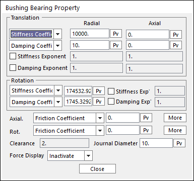
Figure 34.99 Connection of CamRoller - CamRollerShaft
Friction
Standard Friction
Empirical Formula
CamRollerShaft – CamRollerShaftBearing
Fixed Joint
Bushing
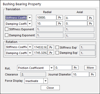
Figure 34.100 Connection of CamRollerShaft – CamRollerShaft Bearing
Friction
Standard Friction
Empirical Formula
Cam Roller
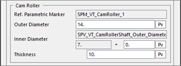
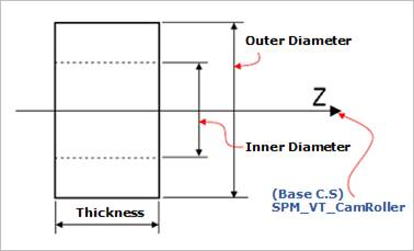
Figure 34.101 Geometric Information for CamRoller
Cam Roller Shaft
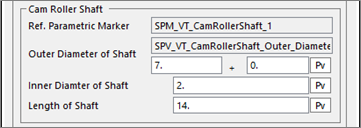
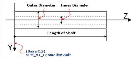
Figure 34.102 Geometric Information for CamRollerShaft
Cam Roller Shaft Bearing
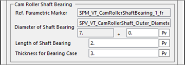
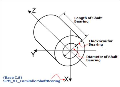
Figure 34.103 Properties of Cam Roller Shaft Bearing
34.2.2.1.2.2. Slipper Type
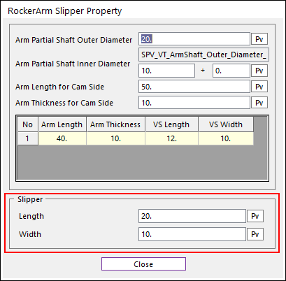
Figure 34.104 RockerArm Slipper Property dialog box
Slipper
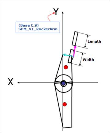
Figure 34.105 Geometric information
Length: Defines a length of the slipper.
Width: Defines a width of the slipper.