6.2.3.2. Inline
An inline joint constraints the origin of action marker to lie on the z-axis of a base marker, as shown in Figure 6.203.
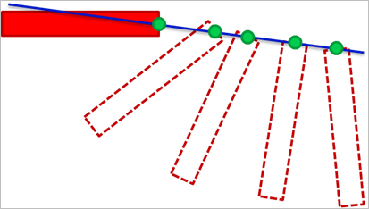
Figure 6.203 Definition of Inline Joint
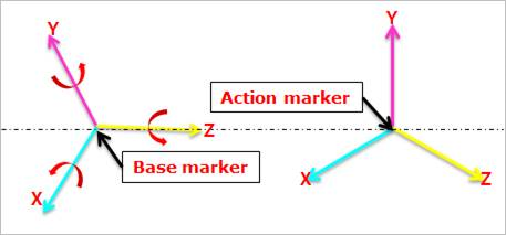
Figure 6.204 Definition of Inline Joint
6.2.3.2.1. Modeling Options
The user can create a joint entity as follows.
Point, Direction
Point: Selects a point on two bodies to define the location of the inline joint.
Direction: Defines the z-axes of base and action markers as the axis of translation.
Body, Body, Point, Direction
Body: Selects a base body of the inline joint.
Body: Selects an action body of the inline joint.
Point: Selects a point to define the location of the inline joint.
Direction: Defines the z-axes of base and action markers as the axis of translation.
6.2.3.2.2. Properties
The user can only define the force display using the Joint page.
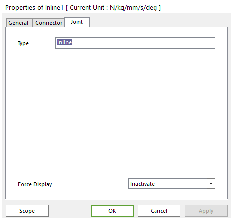
Figure 6.205 Inline property page [Joint page]
Type: Shows the type of joint.
Force Display: Displays the resultant force vector graphically on Working Window.