26.2.3. Linear Guide
A linear guide is dependent on a guide part. If a linear guide is created, a workpiece to line contact is automatically created. Its contact type can be represented as a sphere to line contact. As shown in Figure 26.12, the user first should define whether the contact direction is up or down of the guide, where the up direction is defined as the y-axis of the linear guide reference frame. It cannot be assembled automatically when creating a beam assembly. So, it is recommended to add the linear guide as passing bodies after creating a beam assembly.
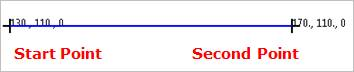
Figure 26.12 Linear Guide
26.2.3.1. Modeling Options
The user can create a linear guide as follows.
Point, Point
Point: Selects a point to define the starting point.
Point: Selects a point to define the ending point.
MultiPoint
MultiPoint: Selects some points.
GuideMotherBody, Point, Point
GuideMotherBody: Selects a body to define the parent body of the linear guide.
Point: Selects a point to define the starting point.
Point: Selects a point to define the ending point.
GuideMotherBody, MultiPoint
GuideMotherBody: Selects a body to define the parent body of the linear guide.
MultiPoint: Selects some points.
26.2.3.2. Properties
The user can modify properties for the linear guide such as geometry information, contact characteristic using GuideLinear property page.
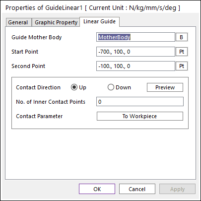
Figure 26.13 GuideLinear property page
Guide Mother Body: Selects the mother body of linear guide by clicking B.
Start Point: Defines the start point of linear guide.
Second Point: Defines the second point of linear guide.
Imaginary Circle Edge: Defines an imaginary Circle Edge on start and/or end point of Linear Guide. The imaginary Circle Edge is a circle shape and located start/end point. And the center point of imaginary Circle Edge is located negative direction of contact (normal) direction. The contact force of the imaginary Circle Edge is added to Linear Guide. User can see the imaginary Circle Edge by clicking Preview.
Edge: Defines Enable(Checked) or Disable(Unchecked) on the Start and/or End point.
Radius: Defines a radius of the imaginary Circle Edge. The user can set a connection with SPV value.
Contact Direction: Allows seeing the direction of contact with the sheet on the arc guide.
No. of Inner Contact Points: Defines the additional contact points in one workpiece.
Contact Parameter: Modifies the contact parameter between assembly (web) and the linear guide. For more information, click here.