29.2.7. Flange
The flange is a geometric entity defined by a frustum. The sloped surface of flange contacts the belt’s side contact nodes, lower side contact nodes or upper side contact nodes of the belt depending upon its configuration. It is typically used in conjunction with a V-belt and defined in conjunction with a roller body. In fact, if you want to use the Surface creation option for the flange, you should create a roller body before making the flange. You select the Point, Distance creation option, the roller body is not needed
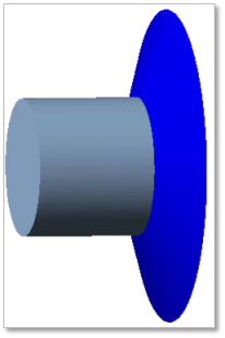
Figure 29.39 Flange geometric entity
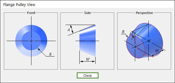
Figure 29.40 Flange dimension information
R |
Radius |
W |
Width |
A |
Angle |
29.2.7.1. Modeling Options
The user can create a flange as follows.
Surface
Surface: Select a face of the roller or crown roller.
Point, Direction, Distance
Point: Selects a point to define the center of the flange.
Direction: Defines a direction for extrusion of the flange.
Distance: Defines a radius of the flange.
29.2.7.2. Properties
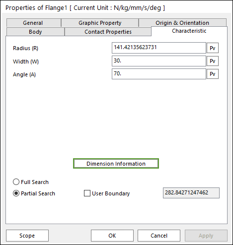
Figure 29.41 Flange property page [Characteristic page]
The Flange property page is shown in Figure 29.41. The parameters are explained below. In order to understand the geometry, refer to Dimension Information.
Radius (R): Enters the radius of flange. The radius is larger than 0.
Width (W): Enters the width of flange. The width is larger than 0.
Angle (A): Enters the angle of flange.
Full Search: If this is checked, all belt bodies are searched for the contact with the flange.
Partial Search: If this is checked, belt bodies within the given boundary are searched for the contact with the flange.
User Boundary: Enters the range of boundary.