39.2.2. Properties
The user can modify the property of EHD Piston Lubrication in the following dialog box.
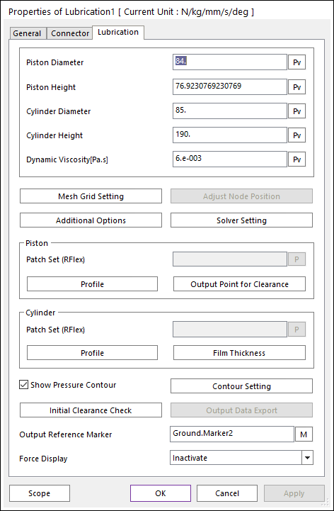
Figure 39.36 EHD Piston Lubrication property page
Piston Diameter: Defines a piston diameter of EHD Piston Lubrication.
Piston Height: Defines a piston height of EHD Piston Lubrication.
Cylinder Diameter: Defines a cylinder diameter of EHD Piston Lubrication.
Cylinder Height: Defines a cylinder height of EHD Piston Lubrication.
Dynamic Viscosity [Pa.s]: Defines lubricant viscosity.
Mesh Grid Setting: Defines mesh grids for Oil Hole and Groove Effects. For more information, click here.
Additional Options: Defines viscosity information and asperity contact information. For more information, click here.
Adjust Node Position: Adjusts RFlex node position on the patch set so that the distance between neutral axis and the node in radial direction is the same as piston or cylinder radius. For more information, click here.
Solver Setting: Defines parameters related to EHD Pressure Convergence.
Piston Section: User can set RFlex patch to define lubrication region of piston. For more information, click here.
Profile: Defines an offset data in angle and height coordinate. User can apply arbitrary piston shape to EHD analysis by setting this offset table data.
Patch set: Selects a patch for lubrication region of action body.
Output Point for Clearance: Specify points on action patch set in angle and height coordinate. Clearance for these points can be output in RecurDyn plot file.
Cylinder Section: User can set RFlex patch to define lubrication region of cylinder. For more information, click here.
Profile: Defines a offset data in angle and height coordinate. User can apply arbitrary cylinder shape to EHD analysis by setting this offset table data.
Patch set: Selects a patch for lubrication region of base body.
Film Thickness: Define oil film thickness by boundary condition.
Show Pressure Contour Animation: If this option is checked, the user can see the EHD contour during the playing animation.
Contour Setting: Defines the EHD Contour information. For more information, click here.
Initial Clearance Check: Check initial clearance in consideration of profile information in order to make sure that user have done the right profile setting. For more information, click here.
Output Data Export: Displays on Scope or exports for the film thickness and file pressure. For more information, click here.
Output Reference Marker: Select reference marker for EHD force result. Default marker is EHD base marker.
Force Display: The user can graphically display the resultant force vector on the Working Window.
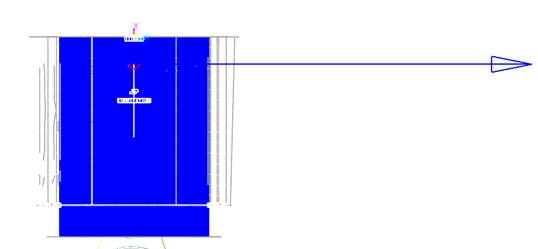
Figure 39.37 Force Display of EHD Piston Lubrication