30.2.6. Multiplex Chain Link
A pair of multiplex chain link consists of roller links and a pin link. An offset link is used when an odd number of chain links is required. A user must create a pair of chain link from which all chain links are copied. Once a pair of chain links is created, it is registered as clone body. The inertial properties of the assembled chain link are automatically duplicated as the values of clone body. A single pin is used to connect roller links and pin links of a chain system in this model. The geometric information provided by a user is used for both display and contact force computation in the solver. Therefore, the multiplex chain link properties must be defined carefully prior to assembling a multiplex chain system.
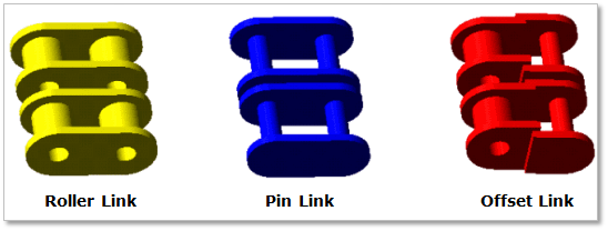
Figure 30.44 Multiplex Chain Link geometry
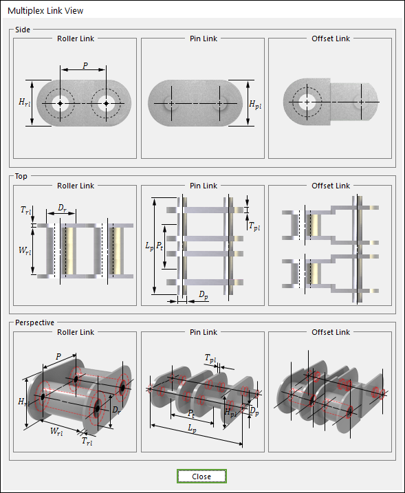
Figure 30.45 Multiplex Chain Link dimension information
P |
Pitch |
Pt |
Transverse Pitch |
Dr |
Roller Diameter |
Wrl |
Width between Roller Link Plate |
Trl |
Thickness of Roller Link Plate |
Hrl |
Height of Roller Link Plate |
Tpl |
Thickness of Pin Link Plate |
Hpl |
Height of Pin Link Plate |
Dp |
Pin Diameter |
Lp |
Pin Length |
30.2.6.1. Modeling Options
The user can create a chain link as follows.
Point, WithDialog
Point: Selects a point on Ground to define the chain link. It doesn’t matter where the chain link is because the created body is a clone body for segment assembly.
WithDialog: Modifies the property for the chain link. The chain link is created with clicking OK.
30.2.6.2. Properties
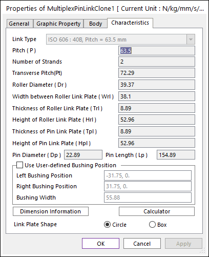
Figure 30.46 Multiplex Chain Link dialog box [Characteristics page]
The Multiplex Chain Link property page is shown in Figure 30.46. The parameters are explained below. In order to understand the geometry, refer to Dimension Information.
Number of Stands: Defines the number of links.
Transverse Pitch (Pt): Defines the distance between links.
All data is same to Roller Chain Link. For more information, click here.