27.2.4. Single Pin Track Link
The track chain system consists of the track links and connecting bushings. There are two types of bushings.
A single pin is used to connect two links of a track chain system in this model. The geometric information provided by a user is used for both display and contact force computation in the solver.
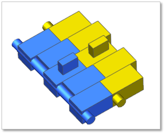
Figure 27.26 Single pin track link (Track link(S)) geometric entity
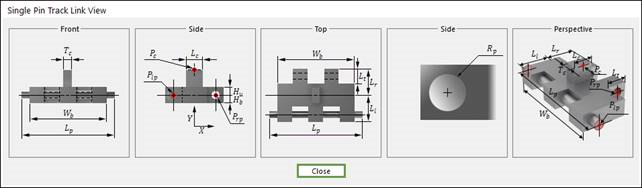
Figure 27.27 Single pin track link (Track link(S)) dimension information
Ll |
Link Body Left Length |
Lr |
Link Body Right Length |
Hu |
Link Body Upper Height |
Hb |
Link Body Lower Height |
Wb |
Link Body Width |
Lt |
Link Body Connector Length |
Lp |
Pin Length |
Rp |
Pin Radius |
Lc |
Centerguide Length |
Tc |
Centerguide Thickness |
Plp |
Left Pin Position |
Prp |
Right Pin Position |
Pc |
Centerguide Position |
27.2.4.1. Modeling Options
The user can create a track link as follows.
Point, WithDialog
Point: Selects a point on Ground to define the track link. It doesn’t matter where the track link is because the created body is a clone body for segment assembly.
WithDialog: Modifies the property for the track link. The track link is created with clicking OK.
27.2.4.2. Properties
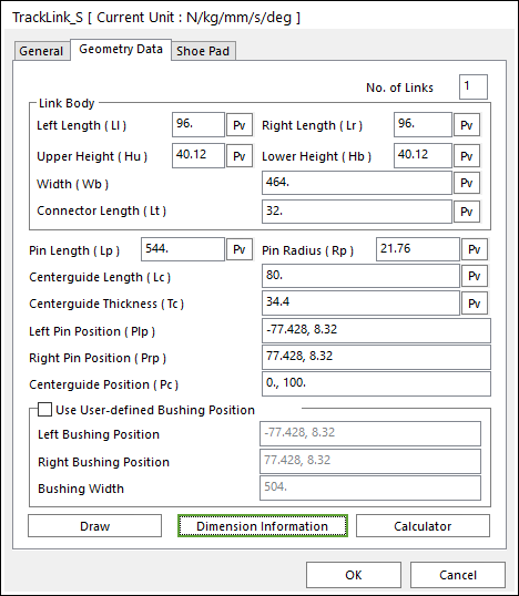
Figure 27.28 Single Pin Track Link property page [Geometry Data page]
The Single Pin Track Link property page is shown in Figure 27.28. The parameters are explained below. In order to understand the geometry, refer to Dimension Information.
No. of Links: Generates a link or links as the number of setting links.
You can generate from one to five.
The generating links can be edited in the clone body.
It is same to apply in Track_HM (Single, Double, Inner Pin Track link) and Track_LM.
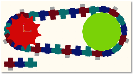
Figure 27.29 Example of three link sets
Link Body: Defines geometric characteristics for Link Body.
Left Length (Ll): Enters the left length of link.
Right Length (Lr): Enters the right length of link.
Upper Height (Hu): Enters the upper height of link.
Lower Height (Hb): Enters the lower height of link.
Width (Wb): Enters the width of link.
Connector Length (Lt): Enters the connector length of link.
Pin Length (Lp): Enters the length of pin body.
Pin Radius (Rp): Enters the radius of pin body.
Centerguide Length (Lc): Enters the length of center guide body.
Centerguide Thickness (Tc): Enters the thickness of center guide body.
Left Pin Position (Plp): Enters the position of left pin body.
Right Pin Position (Rrp): Enters the position of right pin body.
Centerguide Position (Pc): Enters the position of center guide body.
Use User-defined Bushing Position: If it is checked, Bushing force can be defined on different position with pin position.
Left Bushing Position: Defines a base marker position of Bushing force
Right Bushing Position: Defines an action marker position of Bushing force
Bushing Width: Defines a width between two bushing forces.
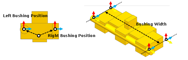
Figure 27.30 Dimension information of user-defined bushing position
Draw: Shows the shoe pad geometry. The user can change the position and size. Also, the shoe pad geometry can be modified in Shoe Pad page.
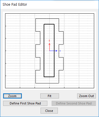
Figure 27.31 Shoe Pad Editor dialog box
Define First Shoe Pad: The user can create a shoe pad by a mouse in Draw dialog box. It can be available in the link.
Define Second Shoe Pad: If Double Shoe Pad in Shoe Pad page is used, this function is activated. The user can create a shoe pad by a mouse in Draw dialog box. It can be available in the link.
Dimension Information: Shows dimension information of the geometry for Roller Link.
Calculator: It is useful for finding specific value to define the relation of between sprockets and Track links. Refer to Calculator.
27.2.4.2.1. Shoe Pad
A track shoe pad is fixed on the track link body. The track shoe pad bears the machine weight and exerts traction to the ground. The shoe pad geometric entity is designed cautiously because it receives different force such as normal force and shear forces. There are two types for vehicle soil interactions. One is hard ground contact and the other is soft soil contact according to Bekker’s theory. Shoe points are needed in hard ground contact and shoe pad mesh is needed in the soft soil.
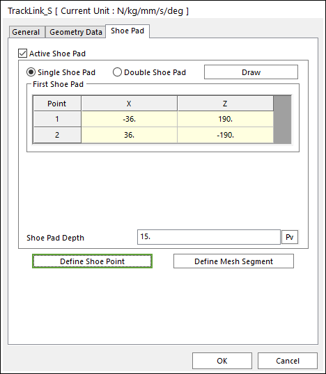
Figure 27.32 Track Link property page [Shoe Pad page]
Active Shoe Pad: If it is checked, shoe pad can be used.
Shoe Pad Shape
There are various types of shoe pad suitable for different work purposes and ground conditions, such as the specially designed shoe pad which has a low ground pressure on the soft ground. In RecurDyn/Track_HM, a single shoe pad and double shoe pad are given.
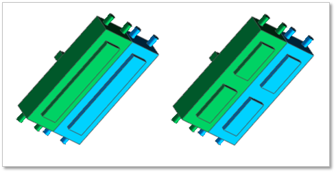
Figure 27.33 Shoe pad shape
Shoe Pad Depth: Defines a depth of the shoe pad.
Define Shoe Point: Shoe points are used to define interaction between the track link body and the hard ground. The default shoe points are supported as follows. Even if the shape of the shoe pad is changed or inactive, the shoe point does not change.
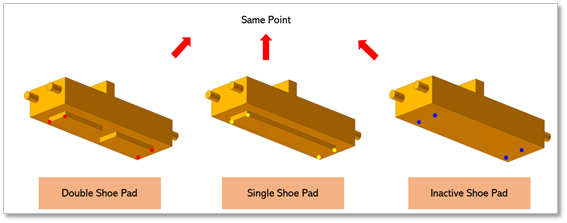
Figure 27.34 Default shoe point
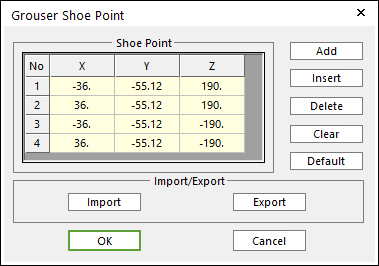
Figure 27.35 Grouser Shoe Point dialog box
X, Y, Z: Defines points.
Add: Adds a row to the end of the table.
Insert: Adds new row to the selected row by the mouse cursor and move the current and lower rows down.
Delete: Deletes the selected row by the mouse cursor and move the lower rows up.
Clear: Deletes all rows in the table.
Default: Resets modified data.
Import: Imports the X, Y, and Z data pairs from a CSV file or a MAT file or a text file. In the case of the text file, the usage of the comma, the tab, and the space can be the delimiter between the three columns in the file. And when using the Excel file, the user can select the Tab-delimited text file output option or the CSV (Comma-Separated Values) file output option to save the Excel file which can be imported.
Export: Exports the X, Y, and Z data pairs to a CSV file or a MAT file or a text file.
Define Mesh Segment: When a vehicle runs on a soft soil, it is not sufficient to define contact by points. Therefore, more points must be provided to form patches on the surface of shoe pad. To achieve this goal, length, height and depth of shoe pad can be meshed into segment.
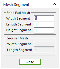
Figure 27.36 Mesh Segment dialog box
Shoe Pad Mesh: If Active Shoe Pad function is checked, Shoe Pad can be meshed to 3 directions.
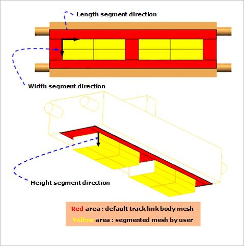
Figure 27.37 Shoe Pad Mesh
Grouser Mesh: If Active Shoe Pad function is not checked, Grouser can be meshed to 2 directions.
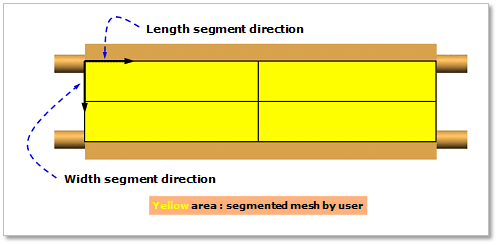
Figure 27.38 Grouser Mesh