6.1.4.4.1. Extrude Solid
It allows the user to create an extruded solid geometric entity from a surface along the user-defined direction.
6.1.4.4.1.1. Modeling Options
The user can create an extruded solid geometry by the following procedure.
Profile, Distance
Profile: Selects a closed-loop profile.
Distance: Defines the distance of the extruding length.
Surface, Direction, Distance
Surface: Select a surface.
Direction: Defines the direction of the extrude.
Distance: Defines the distance of the extruding length.
WithDialog
WithDialog: Extrude dialog box is shown. The solid is created by clicking OK in the Extrude dialog box.
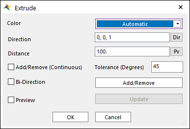
Figure 6.91 Extrude dialog box
Color: Specifies the color of the solid to be created.
Direction: Defines the extruding direction for the extruded solid geometry.
Distance: Defines the distance of the extruding length.
Add/Remove: Selects several faces of any geometries as the user wants to add or remove.
Add/Remove (Continuous): When using Add/Remove, if this option is checked, the connected faces within the degrees are selected together.
Tolerance (Degrees): The angle between the connected two faces.
Bi-Direction: If it is checked, Extrude together in the opposite direction of the extruding solid.
Preview: Previews the solid to be created on Working Window.
Update: Update the preview.
6.1.4.4.1.2. Properties
The user can modify the geometry information using the Extrude Geometry property page.
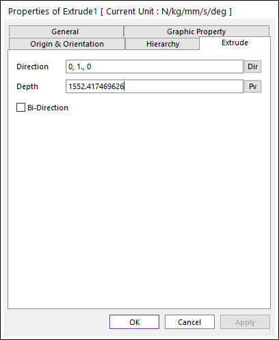
Figure 6.92 Extrude property page
Direction: Defines the direction of the extrude.
Depth: This is a value for the depth of the extruded solid geometry.
Bi-Direction: If it is checked, Extrude together in the opposite direction of the extruding solid.
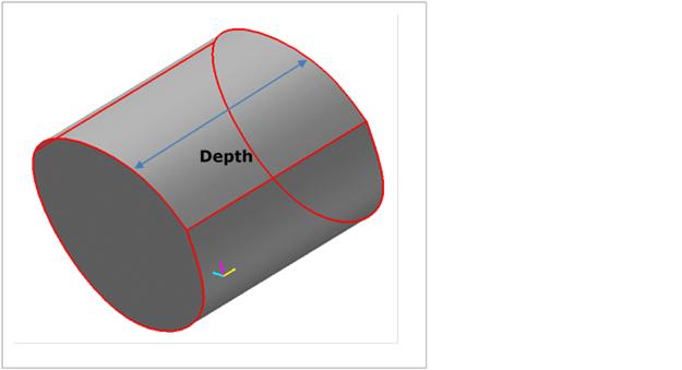
Figure 6.93 Dimensions