28.3.5. CAD Link
The basic parameters of CAD link are same to the basic parameters of Track Link provided in RecurDyn/Track_LM. But, the user should construct a side contact between the CAD sprocket or CAD flanges and the CAD link. The following steps explain how to create a user-defined CAD link.
Terminology
The following figure explains parameters of CAD Link. The user should know the parameter’s value for setting in RecurDyn.
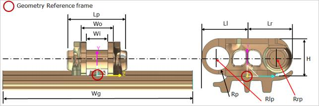
Figure 28.73 The user defined CAD Link geometry
Rp : Pin radius
LP : Pin length
Wi : Track link inner width
Wo : Track link outer width
Ll : Track link left length
Lr : Track link right length
H : Track link height
Rlp : Left pin position
Rrp : Right pin position
Wg : Grouser width
Step to Create a CAD Link
Import or create a user-defined CAD link geometry.
Click the CAD Link icon of the Link group in the Track (LM) tab.
Solid: Selects a desired solid body. (The geometry reference frame of the desired solid must be on the Inertia Marker. Refer to Preparing for CAD Track Entity)
Point: Selects a point where the CAD Link is created.
WithDialog: Inputs user’s CAD link information (Geometry, Grouser Profile). Refer to Track Link.
Geometry Data: Inputs track link’s geometry information.
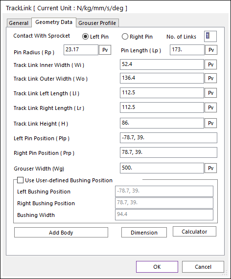
Figure 28.74 CAD Link property page [Geometry Data page]
Use User-defined Bushing Position: If it is checked, Bushing force can be defined on different position with pin position.
Left Bushing Position: Defines a base marker position of Bushing force
Right Bushing Position: Defines an action marker position of Bushing force
Bushing Width: Defines a width between two bushing forces.
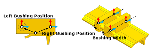
Figure 28.75 Dimension information of user-defined bushing position
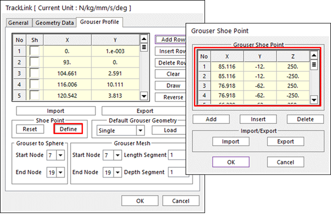
Grouser Profile: Inputs Track Link’s Grouser Profile information. The user can input the own grouser profile data or the user can input the grouser profile data by Add From Geometry function.
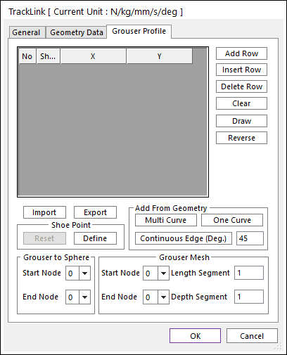
Figure 28.76 CAD Link property page [Grouser Profile page]
Define Shoe Point of Grouser for contact between grouser and ground.
Define a contact surface for the side contact with other Track Flange entities after creating the CAD Link.
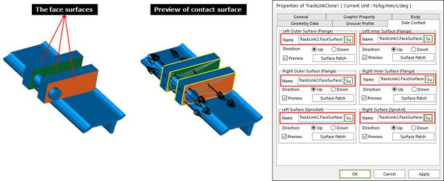
Enter in Clone Body Edit mode.
Create surfaces by using Face Surface. The user can also use other generating surface tools (importing a surface geometry etc…).
Define the contact surfaces in Side Contact page. Refer to Contact Page.
Define the contact characteristic of the Side Contact. Refer to Characteristic Page of Contact.
28.3.5.1. Add From Geometry
Multi Curve
This selects edges by clicking a mouse to define the grouser profile. At first, selects a right edge regarding to the geometry reference frame and then select the other edges in the clockwise direction. The selected edge cannot be clear during operation.
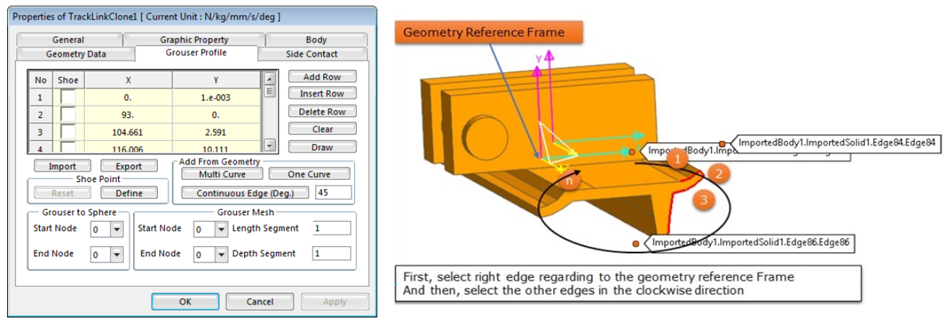
Figure 28.77 How to use the Multi Curve in Add From Geometry
One Curve
This selects a curve that is created as the grouser curve geometry by using Edge Curve. And then, set the number of points to define the grouser profile.
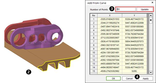
Figure 28.78 How to use One Curve in Add From Geometry group
Continuous Edge (Deg.)
This selects an edge. The connected edges within the tolerance degrees are selected together.