29.8.3. Slip Sensor
This sensor is to measure the difference between the velocity of the Pulley and Belt. The belt segment is that passes between the center position of the Sensor and Pulley. The direction of the sensor is the tangential direction of the center position of the sensor and the center position of the pulley.
The sensing point is different to follow as belt types.
Segment Belt(Flat Belt, V-Belt, Ribbed V-Belt, and Timing Belt): The sensing point is the geometry reference marker, except Belt2D Flat type. The sensing point of the Belt2D Flat type is defined as the center marker position. The geometry reference marker is located at the axis position of the figure on the Dimension Information dialog. In the case of the Timing belt, the geometry reference marker means the profile center.
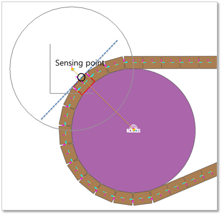
Figure 29.102 Sensing point of the Flat Belt
The sensor output can be computed from the following equation.
\(\mathbf{V}_p\) = [rotational velocity of pulley] * [distance between the center of the pulley and the geometry reference marker of the belt]
\(\mathbf{V}_b\) = [velocity of the geometry reference marker of the belt for the tangential direction of the pulley radius]
Reference Frame (\(\mathbf{A}_{ref} = [f, g, h]\))
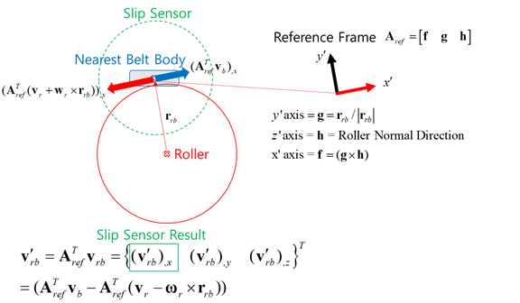
Figure 29.103 Reference Frame of the Slip Sensor
Result_Slip_Sensor = \({{\mathbf{f}}^{T}}({{\mathbf{V}}_{b}}-{{\mathbf{V}}_{p}})\)
Element Belt(Beam, Shell, BeltGroup): The position of the element center of a sensing belt is to be a sensing point.
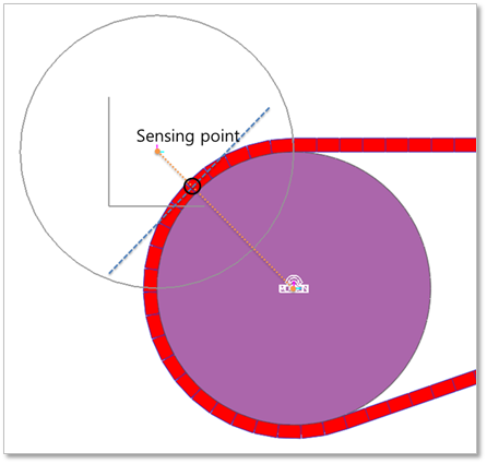
Figure 29.104 Sensing point of the Flat Belt
The sensor output can be computed from the following equation.
\(\mathbf{V}_p\) = [rotational velocity of pulley] * [distance between the center of the pulley and the element center of the belt]
\(\mathbf{V}_b\) = [velocity of the element center of the belt for the tangential direction of the pulley radius]
Reference Frame (\(\mathbf{A}_{ref} = [f, g, h]\)) : Refer the Figure 29.103.
Result_Slip_Sensor = \({{\mathbf{f}}^{T}}({{\mathbf{V}}_{b}}-{{\mathbf{V}}_{p}})\)
29.8.3.1. Modeling Options
The user can create a slip sensor as follows.
RollerBody, Point, Distance
RollerBody: Selects a roller.
Point: Selects a point on a body to define the center of slip sensor.
Distance: Defines a range of region to measure output.
Note
The user should define the sensing target entity by using Slip Sensor property page.
Body, RollerBody, Point, Distance
Body: Selects a body to define the parent body of slip sensor.
RollerBody: Selects a roller.
Point: Selects a point on the assembly to define the center of slip sensor.
Distance: Defines a range of region to measure output.
Note
The user should define the sensing target entity by using Slip Sensor property page.
RollerBody, Assembled Body, Point, Distance
RollerBody: Selects a roller.
Assembled Body: Selects an assembly as a target entity.
Point: Selects a point on the assembly to define the center of slip sensor.
Distance: Defines a range of region to measure output.
Body, RollerBody, Assembled Body, Point, Distance
Body: Selects a body to define the parent body of slip sensor.
RollerBody: Selects a roller.
Assembled Body: Selects an assembly as a target entity.
Point: Selects a point on the assembly to define the center of slip sensor.
Distance: Defines a range of region to measure output.
29.8.3.2. Properties
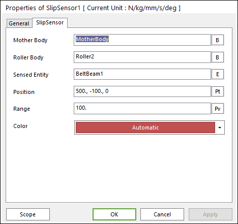
Figure 29.105 Slip Sensor property page
The Slip Sensor property page is shown in Figure 29.105. And its parameters are explained below.
Mother Body: Select the body attached the sensor.
Roller Body: Select the reference pulley to measure the relative velocity.
Sensing Entity: Select the assembly of belt system to measure output.
Position: Enter the center position of sensor.
Range: Enter the range of region to measure the output.
Color: Select the color of sensor.