28.2.7. Track Link
A track chain system consists of the track links and connecting bushings. A single pin is used to connect two links of a track chain system. The user must create one-reference track link from which all track links are copied. Once a track link is created, it is registered as a clone body. The inertial properties of the assembled track link are automatically duplicated to be the same as the values of the clone body. Therefore, the track properties should be defined carefully prior to assembling track chain system. The bushing connecting two track links is automatically created when track chain system is assembled.
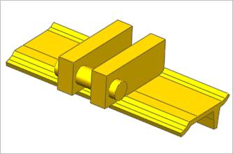
Figure 28.38 Track link geometric entity
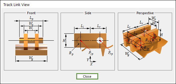
Figure 28.39 Track link dimension information
Rp |
Pin Radius |
LP |
Pin Length |
Wo |
Track Link Outer Width |
Wi |
Track Link Inner Width |
Wg |
Grouser Width |
Ll |
Track Link Left Length |
Lr |
Track Link Right Length |
Rp |
Pin Radius |
H |
Track Link Height |
28.2.7.1. Modeling Options
The user can create a track link as follows.
Point, WithDialog
Point: Selects a point on Ground to define the track link. It doesn’t matter where the track link is because the created body is a clone body for segment assembly.
WithDialog: Modifies the property for the track link. The track link is created with clicking OK.
28.2.7.2. Properties
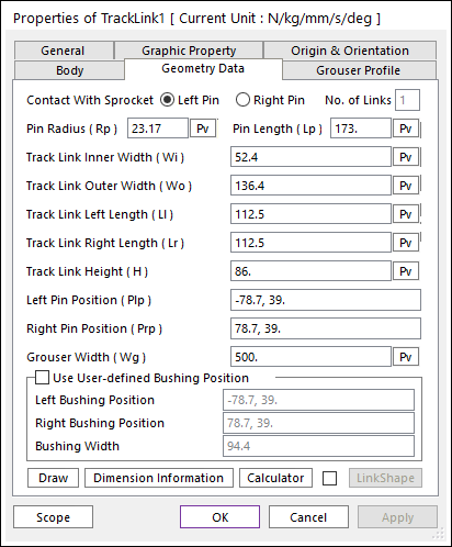
Figure 28.40 Track Link property page [Geometry Data page]
The Track Link property page is shown in Figure 28.40. The parameters are explained below. In order to understand the geometry, refer to Dimension Information.
Contact With Sprocket: The Left/Right Pin of track(LM) link can be selected to calculate more accurate friction force of sprocket with link pin.
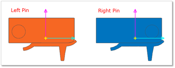
Figure 28.41 The position of Link Pin as Contact With Sprocket option
No. of Links: Defines the number of link sets. This can be available when creating a track link clone body.
Pin Radius (Rp): Enters the pin radius of link.
Pin Length (Lp): Enters the pin length of link.
Track Link Inner Width (Wi): Enters the inner width of link.
Track Link Outer Width (Wo): Enters the outer width of link.
Track Link Left Length (Ll): Enters the left length of link.
Track Link Right Length (Lr): Enters the right length of link.
Track Link Height (H): Enters the height of link.
Left Pin Position (Plp): Enters the left pin position of link.
Right Pin Position (Prp): Enters the right pin position of link.
Grouser Width (Wg): Enters the width of grouser.
Use User-defined Bushing Position: If it is checked, Bushing force can be defined on different position with pin position.
Left Bushing Position: Defines a base marker position of Bushing force
Right Bushing Position: Defines an action marker position of Bushing force
Bushing Width: Defines a width between two bushing forces.
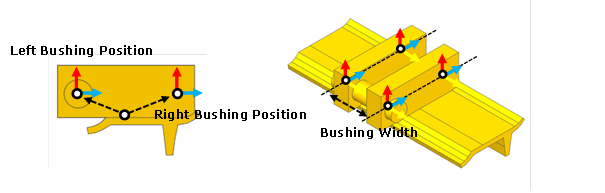
Figure 28.42 Dimension information of user-defined bushing position
Draw: All data must be defined with respect to the grouser marker. You can move points graphically by using the mouse directly.
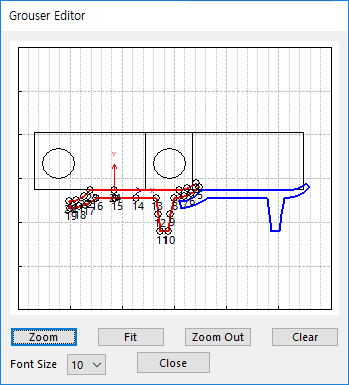
Figure 28.43 Grouser Editor dialog box
Dimension Information: Shows dimension information of the geometry for Roller Link.
Calculator: It is useful for finding specific value to define the relation of between sprockets and Track links. For more information, Refer to Calculator.
Link Shape: The link tread is subjected to uneven wear due to constant contact with the idler and rollers. The link shape can be modified in order to consider the wear effect.
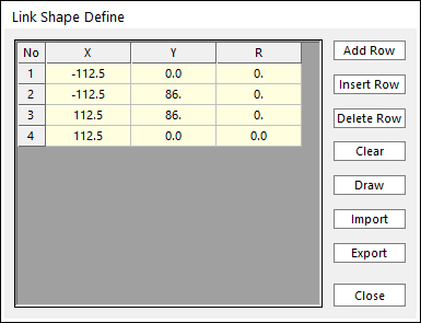
Figure 28.44 Link Shape Define dialog box
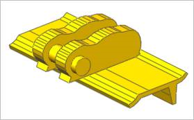
Figure 28.45 Modified link shape
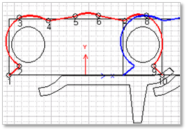
Figure 28.46 Link shape editor
28.2.7.2.1. Grouser Profile
A track grouser is fixed onto the track link by grouser bolts and nuts. The track grouser bears the machine weight and exerts traction to the ground. The grouser geometric entity is designed cautiously because it receives different force such as normal force and shear forces.
There are two types of vehicle-soil interaction. One type is hard ground contact and the other is soft soil contact according to Bekker’s theory. Shoe points are needed in hard ground contact and a grouser mesh is needed in soft soil. Also, grouser nodes have to be chosen if grouser to sphere contact is defined to represent contact with boulders and rocks.
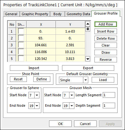
Figure 28.47 Track Link property page [Grouser Profile page]
No: Number of points.
Shoe: Use points.
X, Y: Defines points.
Add Row: Adds a row to the end of the table.
Insert Row: Inserts a row where the cursor is and move the current and later rows down.
Delete Row: Deletes the row where the cursor is and move the later rows up.
Clear: Deletes all rows in the table.
Draw: All data must be defined with respect to the link grouser marker. You can move points graphically by using the mouse directly.
Reverse: Change the direction of the grouser.
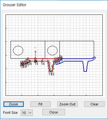
Figure 28.48 Grouser Editor dialog box
Import: Imports the X and Y data pairs from a CSV file or a MAT file or a text file. In the case of the text file, the usage of the comma, the tab, and the space can be the delimiter between the three columns in the file. And when using the Excel file, the user can select the Tab-delimited text file output option or the CSV (Comma-Separated Values) file output option to save the Excel file which can be imported.
Export: Exports the X and Y data pairs to a CSV file or a MAT file or a text file.
Shoe point: Shoe points are used to define interaction between the track link grouser and hard ground. The points are selected from points on the grouser profile by checking on the first column of Grouser Geometric Entity Data on the grouser dialog box.
Reset: Reset the position of shoe points in the following dialog box.
Define: Modify the position of shoe points in the following dialog box.
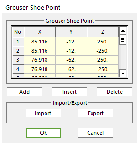
Figure 28.49 Grouser Shoe Point dialog box
X, Y, Z: Defines points.
Add: Adds a row to the end of the table.
Insert: Adds new row to the selected row by the mouse cursor, and move the current and lower rows down.
Delete: Deletes the selected row by the mouse cursor, and move the lower rows up.
Import: Imports the X, Y, and Z data pairs from a MAT file or a text file. In the case of the text file, the usage of the comma, the tab, and the space can be the delimiter between the three columns in the file. And when using the Excel file, the user can select the Tab-delimited text file output option or the CSV (Comma-Separated Values) file output option to save the Excel file which can be imported.
Export: Exports the X, Y, and Z data pairs to a MAT file or a text file.
Default Grouser Geometry: There are various types of grousers suitable for different work purposes and ground conditions, such as the specially designed grouser that has a low ground pressure on soft ground. Single, Double and Triple grousers are available in RecurDyn/Track_LM.
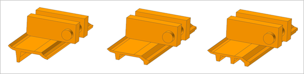
Figure 28.50 Grouser Geometry
Note
If the shoe points are set with a regular form, then the RecurDyn/Solver generates some patch information for the Node Contact of the Track Surface Contact.

Figure 28.51 Contact patches for the Grouser Shoe
Grouser to Sphere: An object such as a stone buried in the ground is often simply defined as a sphere. Contact between a grouser and a sphere is defined by contact points on the grouser profile. If the user defines a Starting Node and an Ending Node of the grouser, all nodes between two nodes become contact points for Grouser to Sphere Contact.
Grouser Mesh: When a vehicle runs on soft soil, it is not sufficient to define contact by points. Therefore, more points must be provided to form patches on the surface of a grouser. To achieve this goal, the length and depth of a grouser can be meshed into segment. For example, when the starting node number is 5 and the ending node number is 13, the length segment is 2 and the depth segment is 4, the track link grouser is meshed as follows.
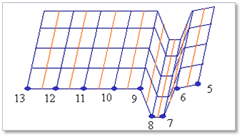
Figure 28.52 Grouser mesh