6.1.4.8. Imprint
In the Imprint group, the user can create curves of the faces on the selected solid or surface entity by using Projection and Intersection. For reference, it is useful to divide a face and create new face surfaces after using Face Surface operation.
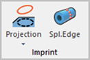
Figure 6.119 Imprint group in the Geometry tab [Body Edit Mode]
6.1.4.8.1. Projection Imprint
It allows the user to imprint curves by projecting the selected curves onto the faces of the selected solid or surface geometric entity.
Modeling Options
The user can work imprint operation with the projection method for one geometric entity by the following procedure.
Solid(Sheet), Wire
Solid(Sheet): Selects a solid or surface geometry to create edges on them.
Wire: Selects a curve to be projected. The selected curve should exist in the space along the normal direction of the face. The imprint operation works in that the face can be divided by the selected curve.
Solid(Sheet), Wire, WithDialog
Solid(Sheet): Selects a solid or surface geometry to create edges on them.
Wire: Selects a curve to be projected.
WithDialog: Imprint Curve dialog box is shown. The curve is projected on the faces of the select solid(sheet) geometry and the edges are created on them by clicking OK in the Imprint Curve dialog box.
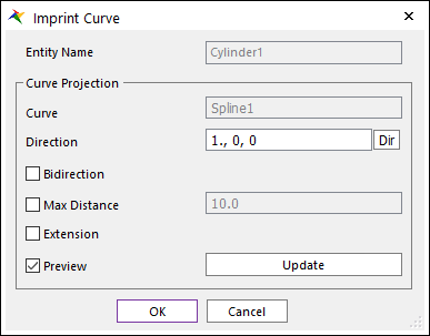
Figure 6.120 Imprint Curve dialog box
Entity Name: Shows the name of the selected entity.
Curve: Shows the name of the selected curve.
Direction: Select a direction to project the selected curve.
Bidirection: The curve is projected both in the direction and the opposite direction.
Max Distance: The curve is projected on the only faces within the distance of the curve and the faces.
Extension: If the curve is short, the imprinted edge is extended to the edges of both sides.
Preview: Previews the curve to be projected on Working Window.
Update: Updates the preview.
6.1.4.8.2. Intersection Imprint
It allows the user to imprint curves that are the intersected lines generated when two bodies interfere with each other.
Modeling Options
The user can work the imprint operation with the intersection method for one geometric entity by the following procedure.
Solid(Sheet), Solid(Sheet)
Solid(Sheet): Selects a solid or surface geometry to imprint the curves on the face.
Solid(Sheet): Selects another solid or surface geometry to intersect with the first selected geometry. Curves are imprinted on the intersected lines between two geometries.
6.1.4.8.3. Intersection with Plane Imprint
It allows the user to imprint curves that are the intersected lines generated when surface or solid geometries interfere with a virtual plane.
Modeling Options
The user can imprint curves on one geometric entity with a virtual plane by the following procedure.
Solid(Sheet), WithDialog
Solid(Sheet): Selects a solid or surface geometry to imprint.
WithDialog: Set the plane to imprint. The imprint curves are created by clicking OK or Apply in the Direct Coordinate Handler dialog box.
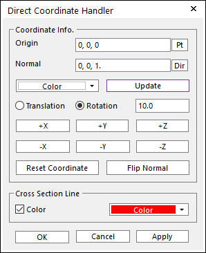
Figure 6.121 Direct Coordinate Handler dialog box
Origin: Defines the origin of a virtual plane.
Normal: Defines the normal vector of a virtual plane.
Color: Selects color of Virtual Plane icon displayed on Working Window.
Update: If Origin and Normal are input directly in this dialog, Update should be clicked to apply these values for the created Virtual Plane.
Translation: If this option is selected, the created Virtual Plane is translated along the axis of the Virtual Plane CM. The user must indicate the amount of translation in the Offset Value input box. To move the entity, use Control Button.
Rotation: If this option is selected, the created Virtual Plane is rotated by the axis of the Virtual Plane CM. The user must indicate the amount of rotation in the Offset Value input box. To rotate the entity, use Control Button. This unit is degree.
Reset Virtual Plane: Resets Virtual Plane to the original origin and orientation.
Flip Normal: If the user clicks Flip Normal, the normal direction (z) is inverted.
Cross Section Line Color: If it is checked, the specified color is applied to the cross-section line. If it is not, normal drawing color is applied to the cross-section line.
Solid(Sheet), MultiFace, WithDialog
Solid(Sheet): Selects a solid or surface geometry to imprint.
MultiFace: Select faces of selected solid or surface geometry. Only selected faces are imprinted.
WithDialog: Set the plane to imprint.
6.1.4.8.4. Radial Pattern Imprint
It allows the user to imprint curves on the surface or solid geometries with a radial pattern. It uses Projection when the user selects Wire geometry. It uses Intersection when the user selects Surface or Solid geometry.
Modeling Options
The user can imprint curves on one geometric entity in a radial pattern by the following procedure.
Solid(Sheet), Solid(Sheet, Wire), WithDialog
Solid(Sheet): Selects a solid or surface geometry to imprint.
Solid(Sheet, Wire): Selects a geometry to construct a radial pattern with.
WithDialog: Sets the rule for the imprint. The imprint curves are created by clicking OK in the Radial Imprint dialog box.
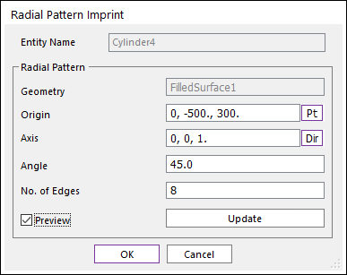
Figure 6.122 Radial Pattern Imprint dialog box
Entity Name: Shows the name of the selected entity to imprint.
Geometry: Shows the selected geometry to construct a radial pattern to imprint
Origin: Defines the origin of the radial pattern.
Axis: Defines the rotation axis of the radial pattern.
Angle: Defines the angle of the one-step rotation.
No. of Edges: Define the number of edges to construct a radial pattern.
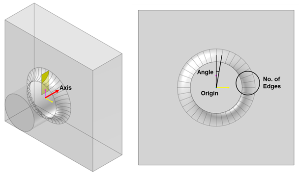
Figure 6.123 Radial Pattern Imprint
Preview: Previews the curve to be imprinted on Working Window.
Update: Updates the preview.
Solid(Sheet), MultiFace, Solid(Sheet, Wire), WithDialog
Solid(Sheet): Selects a solid or surface geometry to imprint.
MultiFace: Select faces of selected solid or surface geometry. Only selected faces are imprinted.
Solid(Sheet, Wire): Selects a geometry to construct a radial pattern with.
WithDialog: Sets the rule for the imprint.
6.1.4.8.5. Offset Edges Imprint
It allows users to imprint edges by offsetting some edges on the surface of a solid geometry.
Modeling Options
The user can imprint edges on one geometric entity by offsetting some edges by the following procedure.
Solid(Sheet), MultiEdge
Solid(Sheet): Selects a solid or surface geometry to imprint.
MultiEdge: Select some edges to offset. Imprint Offset Edges dialog box is shown. The imprint curves are created by clicking OK in the Imprint Offset Edges dialog box.
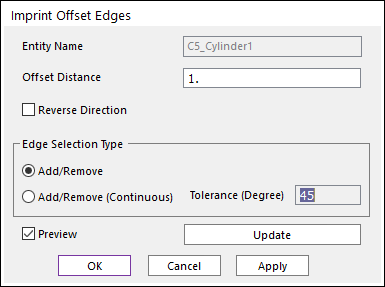
Figure 6.124 Imprint Offset Edges dialog box
Entity Name: Shows the name of the selected entity.
Offset Distance: The distance to offset the selected edges.
Reverse Direction: Change the initial direction of the offset edges.
Add/Remove: Selects several edges of the selected entity as the user wants to add or remove.
Add/Remove (Continuous): When an edge is selected, all of the connected edges within the user-defined tolerance angle are selected at the same time.
Preview: Preview of the offset edges on Working Window.
Update: Updates the preview.
6.1.4.8.6. UV Pattern Imprint
It allows the user to imprint edges on the surface or solid geometries using the UV parameters of the geometries. It split the periodic faces at the UV start parameter and end parameter. The periodic faces cannot be used at the Advanced mesh. If they are split into more than two faces, it would-be four-sided faces and can apply the advanced mesh type (four sides or more than four-sided type) to the faces and control the seeds (No. of elements). The side face of the cylinder and cone and the face of a sphere(ellipsoid) and torus are periodic faces.
Modeling Options
The user can imprint edges on one geometric entity at the UV start parameter and end parameter by the following procedure.
Solid(Sheet)
Solid(Sheet): Selects a solid or surface geometry to imprint.
If the geometry has periodic faces, the faces split into two faces. The following Figure 6.125 shows examples UV pattern applied geometries.
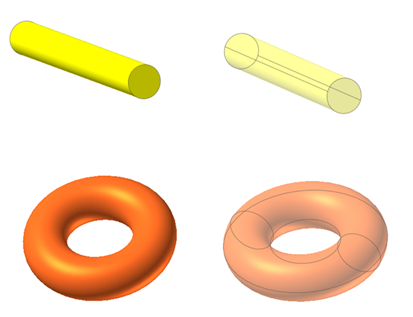
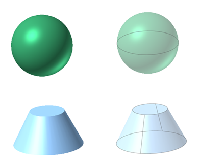
Figure 6.125 The primitive geometries to which UV pattern has been applied
6.1.4.8.7. Quadrangle Imprint
It allows users to imprint quadrangle edges on faces. It is useful to apply the manual mesh to the surface consisting of faces that are not 4-sided.
Modeling Options
The user can imprint quadrangle edges on one geometric entity with a face by the following procedure.
Sheet: Selects a surface geometry with a face to imprint.
If the geometry has one face and one edge or more than two edges, the faces split into the shape of the quadrangle. The following Figure 6.126 shows examples of the quadrangle imprint applied geometries.
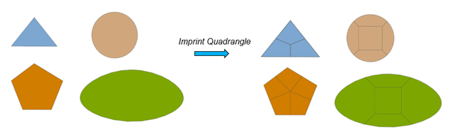
Figure 6.126 Example of Quadrangle Imprint
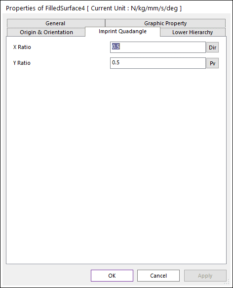
Figure 6.127 Property page of Quadrangle Imprint geometry
X Ratio: The ratio of the inside rectangle width to the circle diameter (or the bounding box width)
Y Radio: The ratio of the inside rectangle height to the circle diameter (or the bounding box height)
The basis of the ratio is the circle in the case of a circle, the circumcircle in the case of a triangle, and the bounding box in other cases.
6.1.4.8.8. Split Edge Imprint
It allows users to imprint points on an edge and split the edge.
Modeling Options
The user can imprint points on an edge of a geometric entity by the following procedure.
Edge, WithDialog
Edge: Selects an edge of a geometry to imprint points.
WithDialog: Selects points to imprint in Imprint Points on Edge dialog box. The imprint curves are created by clicking OK.
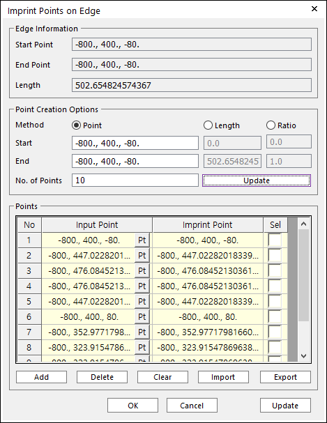
Figure 6.128 Imprint Points on Edge dialog box
Edge Information: This shows the start point, end point, and length of the edge.
Point Creation Options
Method: Points are created between the start and end point, length, and ratio.
No. of Points: These numbers of points are created.
Update: Points are created as input points in the below grid control. And imprint points are calculated. They are on the edge.
Points
Add: Input points are added one by one. The points can be selected in the view and input directly and modified.
Delete: Delete points by deleting the grid rows.
Clear: Delete all the grid and points.
Import: Import points data from files as Input Point. Need to update to use as Imprint Point.
Export: Export points data to files.
Update: Imprint Point are calculated from Input Point. Imprint points must be on the edge. If some input points are not on the edge, then they should be calculated.
6.1.4.8.9. Line Imprint
It allows users to imprint edges on faces using the FFlex line sets and patch sets. The icon is shown only in the mesh mode.
Modeling Options
With FFlex line sets and patch sets, the user can imprint edges on faces of a geometric entity by the following procedure.
Solid(Sheet), Line/Patch Set, WithDialog
Solid(Sheet): Selects a solid or surface geometry to create edges on them.
Line/Patch Set: Selects a line set or patch set to be projected.
Line Set: Line set is projected to the faces and edges are imprinted on the faces.
Patch Set: The outline of the patch set is projected to the faces and edges are imprinted on the faces.
WithDialog: Sets the direction to be projected. The imprint curves are created by clicking OK in the Imprint Line dialog box.
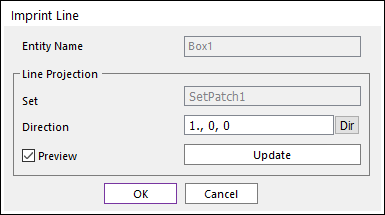
Figure 6.129 Imprint Line dialog box
Entity Name: Shows the name of the selected entity.
Set: Shows the name of the selected line set or patch set.
Direction: Select a direction to project the selected curve.
Direction: Select a direction to project the selected set.
Preview: Previews the curve to be projected on Working Window.
Update: Updates the preview.
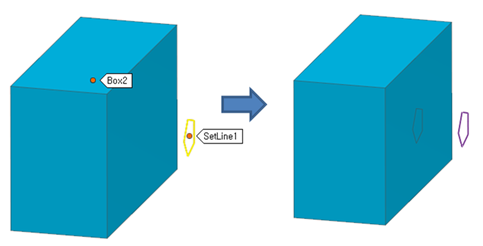
Figure 6.130 Example of Imprint Edge with Line Set
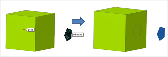
Figure 6.131 Example of Imprint Edge with Patch Set