12.3.8. Remesh
The Local Remesh function allows remeshing the results from RecurDyn/Mesher by changing the element size parameter and fit to CAD geometry option of the specific faces by the user. Especially, when checking the stress/strain results in the coarse mesh region, it is necessary to change the coarse mesh to the fine mesh if the user wants to get more accurate the stress/strain results. The way of remesh is that to change the element length after selecting the face of rigid body which is the original geometry before generating meshes. So, it is possible to use this function just about the flexible body from RecurDyn/Mesher because both the original rigid body and flexible body information should exist. In additional, it is useful for the users to use the Local Remesh function than totally meshing one more after reverting the original rigid body when the user doesn’t want to change the mesh results except for the specific region.
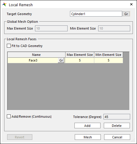
Figure 12.45 Local Remesh dialog box
Target Geometry: Shows a target geometry to apply the local remesh. Any geometries can be selected. Remesh is applied to the mesh of the geometry.
Global Mesh Option: Shows the mesh size for the previous mesh.
Local Remesh Faces: Selects faces to create the fine node or the coarse node by resizing the element length from mesh results. If the user clicks Add, the user can see the shape of CAD geometry before performing the mesh function in the working window. And, if the user clicks the desired faces to remesh, the user can see the highlight part by the yellow color. Also, the user can select the multiple faces by clicking with continuous option and the user should choose Finish Operation on right-click menu by clicking the right mouse button if the user wants to complete to select them. The added faces can be displayed in the Name column in the dialog and the user can remove the selected faces by clicking Delete. In addition, clicking Gr allow modification of the selected faces.
Local Remesh Option: Max Element Size and Min Element Size is the parameters like the Mesh option of Mesh dialog. Local Remesh Option defines the element size parameter to remesh a target face. The Global Mesh Option and the disable edit box is the reference information. The reference information is the last meshed global size parameter from the current mesh results. Figure 12.46 shows that the mesh results are changed by resizing the element length after selecting the target faces.
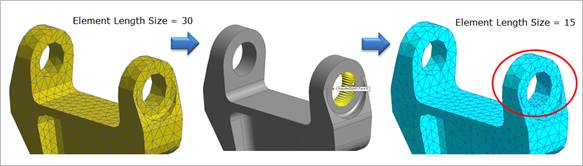
Figure 12.46 Local Remesh Process
Fit to CAD Geometry: Provides the results of more precise mesh when performing Remesh. The basic concept of RecurDyn/Mesher is to perform the mesh base on the graphical tessellation data (triangular input) of the CAD geometry. So, the user is dependent on the mesh results, not on CAD geometry because the user performs the remesh function from the current mesh results. In this time, the user can get the more correct results to the CAD geometry if the user checks the Fit to CAD Geometry option. But, if the user checks this option, the earlier remesh results are not applied and the original mesh results are changed. So, the results of faces that the user does not perform to remesh are changed. The remesh results by the Fit to CAD Geometry option is shown as Figure 12.45. The user can easily understand it in comparison with Figure 12.47.
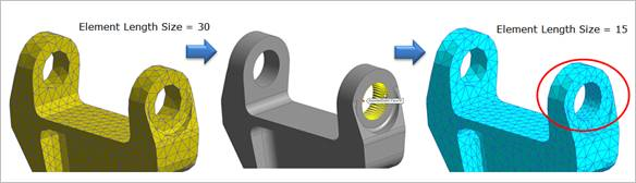
Figure 12.47 Local Remesh Results with Fit to CAD Geometry option
Revert: Applies to return to the original mesh result.
Mesh: Executes the mesh. You can see the mesh information such as the number of nodes and elements in Message Window after finishing to mesh geometry.
Note