12.3.6. Advanced Mesh
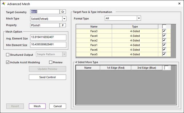
Figure 12.28 Advanced Mesh dialog box
Target Geometry: Selects the geometry which performs the mesh function.
Mesh Type: Selects the element type when you perform the mesh function. RecurDyn/Mesher supports 6 element types as follows.
Shell – Shell3 (Tria3), Shell4 (Quad4)
Note
Shell4 (Quad4) is not pure Quad. But, Quad4 dominant (Tri3 – Quad4 mixed)
Solid – Solid4 (Tetra4), Solid10 (Tetra10), Solid8 (Hexa8)
Property: Selects the applied property to the selected element type.
When you enter the Mesh mode at first, the Property types of Beam, Shell and Solid are created automatically. So, you can select Property without creating Property.
The default properties have a material defined as the general steel of isotropic materials. So, if you want to define the material as the physical model, you must change the properties by clicking Data in the Material dialog box.
Mesh Option: Defines the length of created element when the mesher performs the auto- mesh function. The default value is internally defined. But, the use after modifying the value is recommended as follows.
Avg. Element Size: Sets the average size of elements. This value is the average length of a side to the element. It does not control the defined value absolutely and perfectly. It is used in rough parts of a geometry entity. The default value is 2.5% of diagonal length to the bounding box of geometric entity.
Min Element Size: Sets the minimum size of elements. This value is the minimum length of a side to the element. It does not control the defined value absolutely and perfectly. It is used in fine parts which are difficult to mesh using maximum size in a geometry entity.
Note
Max. Element size is automatically determined by Avg. Element Size and Min Element Size. (Max. Element Size = Avg. Element Size + (Avg. Element size – Min Element Size) ) The default value of Min. Element size is 0.75 * Avg. Element size.
Structured Output: Defines the patterns of created element regularly to improve the quality of mesh when the mesher performs the auto–mesh function. For more information, click here.
Target Face & Type Information: Displays the information of several faces in a CAD geometry to perform Advanced Mesh. For more information, click here.
Preview
If the user uses this function when performing Advanced Mesh by the element size parameter, the use can see the information of node position which is distributed to the edge of each face (It is called Seed) before performing the mesh. So, the user can get the desired mesh result by resetting the element size parameter.
Revert: Returns the original geometric entity.
Mesh: Executes the mesh. You can see the mesh information such as the number of nodes and elements in Message Window after finishing to mesh geometry.
Seed Control: Control the number of elements on the selected edges. The default number of elements is the edge length divided by the mesh size.
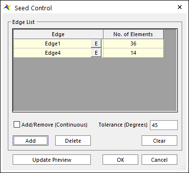
Figure 12.29 Seed Control dialog box
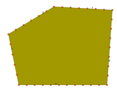
Figure 12.30 Preview of Seed Control: The number of elements is shown.
Note
In the case of the 4-Sided, Circle, 4-Sided More types by setting Element Size Parameter, the user may get the desired mesh result. If the user performs Advanced Mesh assuming that various faces are set the 4-Sided type, the node distribution can be failed because of incorrect setting for the selected Element Size Parameter and the length of edge. To get the satisfied mesh result, the user should set the smaller value to Min. Size Parameter. For example, in case of the 4-Sided type or 4-Sided More type, if the number of elements that the longest edge or edge set is divided by Avg. Size Parameter or the number of elements that the shortest edge or edge set is divided by Min. Size Parameter can be divided by the specific value, the user can increase the rate of success for performing the mesh.