20.6.13.3. PMSM Drive
PMSM Drive block is the block to model PMSM and Controller to control PMSM. Refer to PMSM (Permanent Magnet Synchronous Machine).
Dialog box
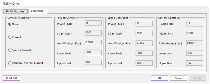
Figure 20.194 PMSM Drive dialog box
Parameter(s) |
Description |
Kcp_id |
Proportional gain of PMSM Current Controller. |
Kci_iq |
Integral gain of PMSM Current Controller. |
Kca_id |
Anti-Windup gain of PMSM Current Controller. |
Lower Limit |
Output minimum value (Voltage) of PMSM Current Controller. |
Upper Limit |
Output maximum value (Voltage) of PMSM Current Controller. |
Parameter(s) |
Description |
Ksp |
Proportional gain of PMSM Speed Controller. |
Ksi |
Integral gain of PMSM Speed Controller. |
Ksa |
Anti-Windup gain of PMSM Speed Controller. |
Lower Limit |
Output minimum value (q-axis Current) of PMSM Speed Controller. |
Upper Limit |
Output maximum value (q-axis Current) of PMSM Speed Controller. |
Parameter(s) |
Description |
Kpp |
Proportional gain of PMSM Position Controller. |
Kpi |
Integral gain of PMSM Position Controller. |
Kpa |
Anti-Windup gain of PMSM Position Controller. |
Lower Limit |
Output minimum value (Speed) of PMSM Position Controller. |
Upper Limit |
Output maximum value (Speed) of PMSM Position Controller. |
20.6.13.3.1. Input Port and Output Port of PMSM Drive
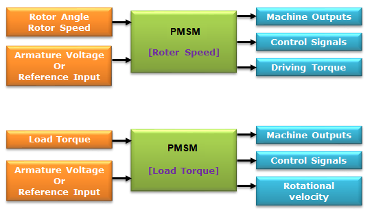
Input signals
Table 20.135 1st Port Input data Mode
Input signal of 1st Port
Rotor Speed
Rotor Angle, Rotor Speed
Load Torque
Load Torque
Table 20.136 2nd Port Controller Mode
Input signal of 2nd Port
None
Phase A, B, C Voltages
Current
Current Reference
Speed + Current
Speed Reference
Position + Speed + Current
Position Reference
Output signals
Table 20.137 1st Port No
Signal
Description
Unit
1
\(\theta\)
Is the rotor angle
rad
2
\(\omega\)
Is the rotor angular velocity
rad/s
3
\({{i}_{a}}\)
Is the stator current of phase a
A
4
\({{i}_{b}}\)
Is the stator current of phase b
A
5
\({{i}_{c}}\)
Is the stator current of phase c
A
6
\({{i}_{ds}}\)
Is the stator current of d-axis
A
7
\({{i}_{qs}}\)
Is the stator current of q-axis
A
8
\({{V}_{d}}\)
Is the stator voltage of d-axis
V
9
\({{V}_{q}}\)
Is the stator voltage of q-axis
V
10
\({{T}_{e}}\)
Is the generated electrical torque
N.m
Table 20.138 2nd Port Controller Mode
Output signals of 2nd Port
None
None
Current
d-axis Voltage, q-axis Voltage
Speed + Current
d-axis Voltage, q-axis Voltage, Reference q-axis Current
Position + Speed + Current
d-axis Voltage, q-axis Voltage, Reference q-axis Current, Reference speed.
Table 20.139 3rd Port Input data Mode
Output signal of 3rd Port
Rotor Speed
Driving Torque
Load Torque
Rotor Rotational Velocity
20.6.13.3.2. PMSM Controller
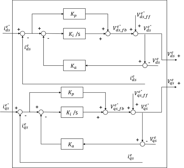
Figure 20.195 Current Controller
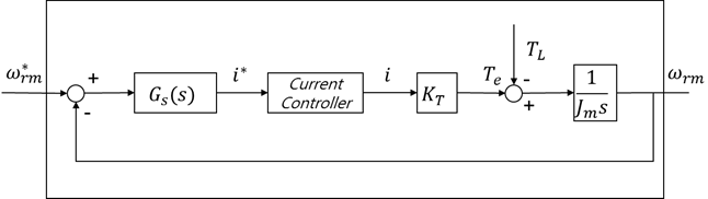
Figure 20.196 Speed + Current Controller
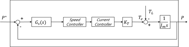
Figure 20.197 Position Controller
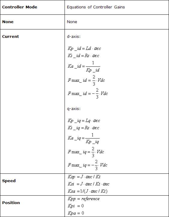
20.6.13.3.3. Design of Controller