6.3.2.7. Bushing
A bushing force provides a full, six degree-of-freedom (DOF) connector between two bodies. The bushing characteristics are defined by the stiffness and damping coefficients for all six DOFs. It defines the characteristic of bushing by the stiffness parameter and the damping parameter as the spring force or the rotational spring force.
6.3.2.7.1. Modeling Options
The user can create a force entity as follows.
Point
Point: Selects a point on two bodies to define the location of bushing force.
Body, Body, Point
Body: Selects a base body of bushing force.
Body: Selects an action body of bushing force.
Point: Selects a point to define the location of bushing force.
Body, Body, Point, Direction
Body: Selects a base body of bushing force.
Body: Selects an action body of bushing force.
Point: Selects a point to define the location of bushing force.
Direction: Defines the direction of z-axis for two markers.
Body, Body, Point, Point
Body: Selects a base body of bushing force.
Body: Selects an action body of bushing force.
Point: Selects a point to define location of bushing force.
Point: Selects a point to define location of bushing force. The bushing force is created between the two selected points.
Body, Body, Point, Point, Direction
Body: Selects a base body of bushing force.
Body: Selects an action body of bushing force.
Point: Selects a point to define location of bushing force.
Point: Selects a point to define location of bushing force. The bushing force is created between the two selected points.
Direction: Defines the direction of z-axis for two markers.
6.3.2.7.2. Properties
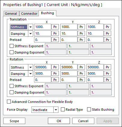
Figure 6.262 Bushing property page
The magnitude of the busing force is calculated according to the following equations:
\(\begin{aligned} & \left[ \begin{matrix} {{F}_{ax}} \\ {{F}_{ay}} \\ {{F}_{az}} \\ {{T}_{ax}} \\ {{T}_{ay}} \\ {{T}_{az}} \\ \end{matrix} \right]=-\left[ \begin{matrix} {{K}_{11}} & 0 & 0 & 0 & 0 & 0 \\ 0 & {{K}_{22}} & 0 & 0 & 0 & 0 \\ 0 & 0 & {{K}_{33}} & 0 & 0 & 0 \\ 0 & 0 & 0 & {{K}_{44}} & 0 & 0 \\ 0 & 0 & 0 & 0 & {{K}_{55}} & 0 \\ 0 & 0 & 0 & 0 & 0 & {{K}_{66}} \\ \end{matrix} \right]\left[ \begin{matrix} {{x}^{k1}} \\ {{y}^{k2}} \\ {{z}^{k3}} \\ \theta _{ab1}^{l1} \\ \theta _{ab2}^{l2} \\ \theta _{ab3}^{l3} \\ \end{matrix} \right]-\left[ \begin{matrix} {{C}_{11}} & 0 & 0 & 0 & 0 & 0 \\ 0 & {{C}_{22}} & 0 & 0 & 0 & 0 \\ 0 & 0 & {{C}_{33}} & 0 & 0 & 0 \\ 0 & 0 & 0 & {{C}_{44}} & 0 & 0 \\ 0 & 0 & 0 & 0 & {{C}_{55}} & 0 \\ 0 & 0 & 0 & 0 & 0 & {{C}_{66}} \\ \end{matrix} \right]\left[ \begin{matrix} {{V}_{x}}^{m1} \\ {{V}_{y}}^{m2} \\ {{V}_{z}}^{m3} \\ \omega _{ab1}^{n1} \\ \omega _{ab2}^{n2} \\ \omega _{ab3}^{n3} \\ \end{matrix} \right]+\left[ \begin{matrix} {{F}_{1}} \\ {{F}_{2}} \\ {{F}_{3}} \\ {{T}_{1}} \\ {{T}_{2}} \\ {{T}_{3}} \\ \end{matrix} \right] \\ & \\ & {{F}_{b}}=-{{F}_{a}} \\ & {{T}_{b}}=-{{T}_{a}}-L\times {{F}_{a}} \\ \end{aligned}\)
Where, the inputs into the equation are defined in the following table:
Stiffness X,Y, Z(Translation) |
\({{K}_{ii}}(i=1,2,3)\) |
Enter the coefficient that determines spring stiffness, namely the change in bushing displacement from the equilibrium position as a function of the force in the respective direction (units are force/length). |
Stiffness Spline X, Y, Z (Translation) |
Fill in values of spring lengths and spring forces that covers the range of extension and retraction of the spring. For more information, click here. |
|
Damping X, Y,Z (Translation) |
\({{C}_{ii}}(i=1,2,3)\) |
Enter the coefficient that determines the damping force given the velocity of motion in the bushing in the respective direction (units are force-time/length). |
Damping SplineX, Y, Z (Translation) |
Fill in values of spring velocities and damping forces that covers the range of positive and negative velocities in the spring. For more information, click here. |
|
Preload X, Y,Z (Translation) |
\({{F}_{1}},{{F}_{2}},{{F}_{3}}\) |
Specify an extra load or force in the spring in the respective direction. The force in the bushing in its equilibrium position is the Preload. |
Stiffness Exponent (Translation) |
\(ki(i=1,2,3)\) |
Specify an exponent that is applied to the rate of change of the spring length (spring velocity). |
Damping Exponent (Translation) |
\(mi(i=1,2,3)\) |
Specify an exponent that is applied to the velocity of motion in the bushing. |
Displacement X, Y, Z (Translation) |
\(x,y,z\) |
Translational displacements of the action marker with respect to the base marker. |
Velocity X, Y,Z (Translation) |
\({{V}_{x}},{{V}_{y}},{{V}_{z}}\) |
Translational velocities of the action marker with respect to the base marker |
Stiffness X,Y, Z (Rotation) |
\({{K}_{ii}}(i=4,5,6)\) |
Enter the coefficient that determines spring stiffness, namely the change in bushing displacement from the equilibrium position as a function of the force in the respective direction (units are force-length/radian). |
StiffnessSpline X, Y, Z (Rotation) |
Fill in values of spring rotations and spring torques that cover the range of rotation of the spring. For more information, click here. |
|
Damping X, Y,Z (Rotation) |
\({{C}_{ii}}(i=4,5,6)\) |
Enter the coefficient that determines the damping force given the velocity of motion in the bushing in the respective direction (units are force-length-time/radian). |
Damping SplineX, Y, Z (Rotation) |
Fill in values of spring rotational velocities and damping torques that covers the range of positive and negative velocities in the spring. For more information, click here. |
|
Pre load X, Y,Z (Rotation) |
\({{T}_{1}},{{T}_{2}},{{T}_{3}}\) |
Specify an extra load or force in the spring in the respective direction. The force in the bushing in its equilibrium position is the Preload. |
Stiffness Exponent****(Rotation) |
\(li(i=1,2,3)\) |
Specify an exponent that is applied to the change in bushing displacement from the equilibrium position. |
Damping Exponent (Rotation) |
\(ni(i=1,2,3)\) |
Specify an exponent that is applied to the velocity of motion in the bushing. |
Displacement X, Y, Z (Rotation) |
\({{\theta }_{ab1}},{{\theta }_{ab2}},{{\theta }_{ab3}}\) |
Rotational displacements of the action marker with respect to the base marker. |
Velocity X, Y,Z (Rotation) |
\({{\omega }_{ab1}},{{\omega }_{ab2}},{{\omega }_{ab3}}\) |
Rotational velocities of the action marker with respect to the base marker |
Advanced Connection for Flexible Body: If user selects this option, the bushing force is directly connected two body not using virtual body connection. If there’s no flexible body (RFlex or FFlex), this option is ignored.
Force Display: Displays the resultant force vector graphically on Working Window.
Radial Type: If the user checks Radial Type option, a translational x direction of bushing force and a translational y direction of bushing force are combined. The magnitude of the radial type busing force is calculated according to the following equations:
\(\begin{aligned} & \left[ \begin{matrix} {{F}_{ax}} \\ {{F}_{ay}} \\ {{F}_{az}} \\ {{T}_{ax}} \\ {{T}_{ay}} \\ {{T}_{az}} \\ \end{matrix} \right]=-\left[ \begin{matrix} {{K}_{12}} & 0 & 0 & 0 & 0 & 0 \\ 0 & {{K}_{12}} & 0 & 0 & 0 & 0 \\ 0 & 0 & {{K}_{33}} & 0 & 0 & 0 \\ 0 & 0 & 0 & {{K}_{44}} & 0 & 0 \\ 0 & 0 & 0 & 0 & {{K}_{55}} & 0 \\ 0 & 0 & 0 & 0 & 0 & {{K}_{66}} \\ \end{matrix} \right]\left[ \begin{matrix} {{r}_{1}} \\ {{r}_{2}} \\ {{z}^{k3}} \\ \theta _{ab1}^{l1} \\ \theta _{ab2}^{l2} \\ \theta _{ab3}^{l3} \\ \end{matrix} \right]-\left[ \begin{matrix} {{C}_{12}} & 0 & 0 & 0 & 0 & 0 \\ 0 & {{C}_{12}} & 0 & 0 & 0 & 0 \\ 0 & 0 & {{C}_{33}} & 0 & 0 & 0 \\ 0 & 0 & 0 & {{C}_{44}} & 0 & 0 \\ 0 & 0 & 0 & 0 & {{C}_{55}} & 0 \\ 0 & 0 & 0 & 0 & 0 & {{C}_{66}} \\ \end{matrix} \right]\left[ \begin{matrix} {V}^{1} \\ {V}^{2} \\ {{V}_{z}}^{m3} \\ \omega _{ab1}^{n1} \\ \omega _{ab2}^{n2} \\ \omega _{ab3}^{n3} \\ \end{matrix} \right]+\left[ \begin{matrix} {{F}_{1}} \\ {{F}_{2}} \\ {{F}_{3}} \\ {{T}_{1}} \\ {{T}_{2}} \\ {{T}_{3}} \\ \end{matrix} \right] \\ \end{aligned}\)
\(\phi = \tan^{-1}\left ( y,x \right )\)
\(K_{12}=Linear Interpolation Function\left ( \phi ,K_{11},K_{22} \right )\)
\(C_{12}=Linear Interpolation Function\left ( \phi ,C_{11},C_{22} \right )\)
\(k_{r}=\left ( k_{2}+ k_{2} \right )/2\)
\(c_{r}=\left ( c_{2}+ c_{2} \right )/2\)
\(r_{1}=\left ( \sqrt{x^{2}+y^{2}} \right )^{k_{r}}\cdot u_{ab1}\)
\(r_{2}=\left ( \sqrt{x^{2}+y^{2}} \right )^{k_{r}}\cdot u_{ab2}\)
\(V_{1}=\left ( \sqrt{V_{x}^{2}+V_{y}^{2}} \right )^{c_{r}}\cdot v_{ab1}\)
\(V_{2}=\left ( \sqrt{V_{x}^{2}+V_{y}^{2}} \right )^{c_{r}}\cdot v_{ab2}\)
- where,
Static Bushing: If the user checks Static Bushing option, a bushing force is used only executing Static analysis. When executing Dynamic/Kinematic analysis, a bushing force is not used.
Note
When the relative angle is evaluated, RecurDyn/Solver assumes that the difference of the rotation range for the x-axis and y-axis is small.