6.1.2.3. Origin and Orientation Page
This page allows the user to modify the origin and orientation of the body reference frame of a body only in Assembly Mode.
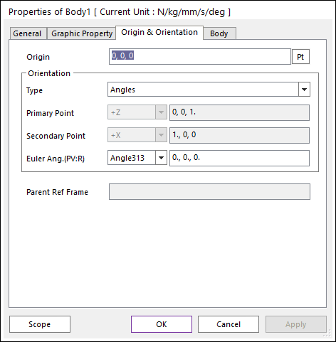
Figure 6.13 Body property page [Origin and Orientation page]
Origin: Defines the reference point of the body reference frame.
Orientation
Type: Selects the orientation type as Angles or Coordinate.
Angles: If the Angle type is selected, the user can use either 321 or 313 Euler Angles
Coordinate: If the Coordinate type is selected, the user can define the orientation of the Body Reference Frame by defining the primary and secondary points.
Primary Point and Secondary Points: Defines the direction vector of the selected axis such as +X, +Y, +Z, -X, -Y, and -Z by writing three components (X, Y, Z) or selecting a point. When two user-defined axes are not orthogonal, the axis of Primary Point is defined as the user-defined point information with higher priority, and then the axis of Secondary Point is adjusted automatically so that two axes can be orthogonalized.
Euler Angle: Selects Angle 321 or Angle 313.
The Euler angle can be defined as a parametric value. For reference, because the unit of Parametric Value is radian, if the user wants to use the Degree unit, the user should append the “D” character to the value such as “90D”.
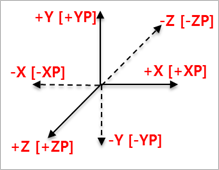
Figure 6.14 XP, YP, and ZP