28.4.2.4. Bushing Force
In practice, the single pin track link system of low mobility tracked vehicle is modeled as a series of bodies connected by bushings around the link pins which are inserted into a shoe body with a radial pressure to reduce rattling of the pin. The bushings tend to reduce the high impulsive contact forces by providing cushion and reducing the relative angle between the track links. In this bushing force, a continuous force model is used to represent the pin connections. This force model is a non-linear function of the coordinates of the two links.
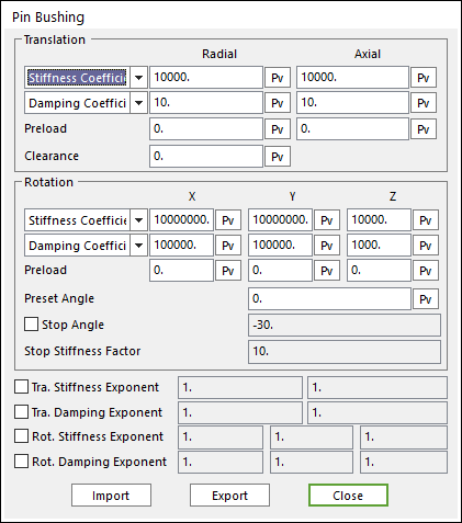
Figure 28.98 Pin Bushing dialog box
The Pin Bushing is a radial type bushing. For more information, click here.
Clearance
When rubber bushings wear out, the connections develop clearance in the radial direction. In such a case, the connections no longer behave like perfect bushings. The user is easily able to model bushings with a gap by entering a non-zero value into the clearance field.
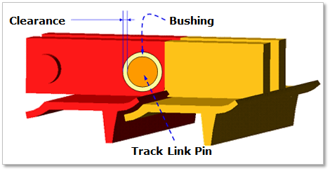
Figure 28.99 Clearance
Preset Angle
Bushings are intentionally inserted initially with an angle between the track links to prevent an excessive rotational deformation of the bushings when they pass around the sprocket or idler. For example, if the rotation of one link relative to its adjacent link is 14 degrees while passing around the sprocket, the pin bushing rotates only 7 degrees if the initial preset angle is 7 degrees instead of 14. As a result, the pin bushing experiences only torque equivalent to the 7 degrees of deformation (plus and minus). This increases the life cycle of the rubber bushing pin. The preset angle can also be used to define the characteristic of rubber track, which at rest tends to form a circle.
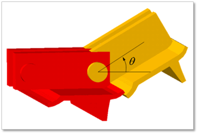
Figure 28.100 Preset angle
Stop Angle
Two adjacent grousers often come in contact. As a result, the relative rotation of two grousers is limited. This rotational limitation can be modeled by a stop angle. The stop angle can be defined by checking in Stop angle and entering Stop stiffness factor with the pin bushing dialog box. Therefore, the Bending back about z-axis direction is prevented by Stop angle. Stop angle is modeled by multiplying stiffness coefficient by Stop stiffness factor when the rotational angle of Z-axis exceeds the stop angle value.
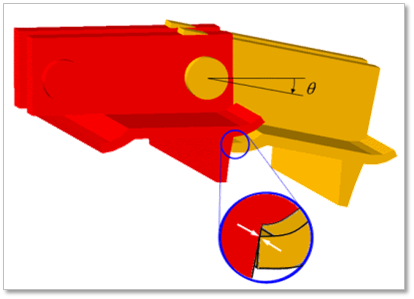
Figure 28.101 Stop angle