33.2.2. Connecting Rod
A connecting rod is composed of a single body.
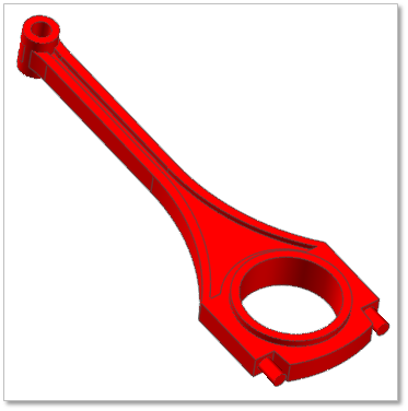
Figure 33.19 Connecting Rod
33.2.2.1. Modeling Options
Click the Con.Rod icon of the Piston group in the Piston tab. The user can see the Crank Component - ConRod dialog box.
The user can select the position where the connecting rod is created in Component Index.
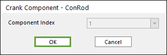
Figure 33.20 Crank Component - ConRod dialog box
Click OK.
33.2.2.2. Properties
Click right mouse button on the connecting rod body to choose Properties of the connecting rod. The user can modify the property of connecting rod in the following dialog.
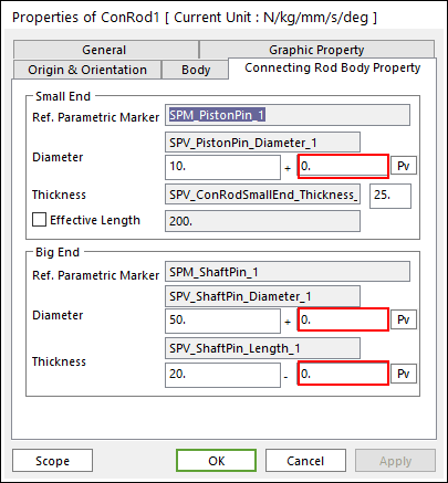
Figure 33.21 Connecting Rod property page
The user can make Clearance between bodies using the value in the red box
Reference Parametric Marker of the big eye and small eye: Controls the position of the center of big eye and small eye each. It is also the special parametric marker.
Diameter and Thickness of the big eye and small eye: A re also special parametric values. The user can modify the parametric value in this section.
These values are enlisted in the special parametric value list.
The user can check the name of each special parametric value.
Effective Length: Allows the user to modify the value, RecurDyn automatically updates the position of the reference parametric marker of small eye based on the effective length value. In this process the reference parametric marker of big eye is fixed because the big eye is the base point of connecting rod.
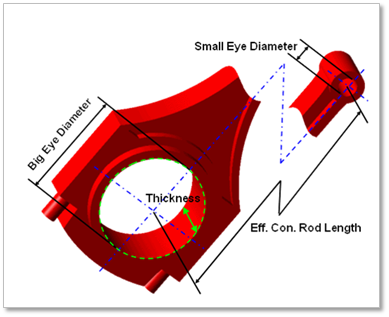
Figure 33.22 Geometrical information of connection rod