6.3.2.9. Matrix
A matrix force provides a full, six degree-of-freedom (DOF) connector between two bodies. The matrix characteristics are defined by the stiffness and damping coefficients for all six DOFs. It defines the characteristic of bushing by the six-by-six stiffness matrix and the six-by-six damping matrix.
6.3.2.9.1. Modeling Options
The user can create a force entity as follows.
Point, Point
Point: Selects a point on a base body. This point defines a location on which the reaction force is applied.
Point: Selects a point on an action body. This point defines a location on which the action force is applied.
Body, Body, Point, Point
Body: Selects a base body of matrix force.
Body: Selects an action body of matrix force.
Point: Selects a point on a base body. This point defines a location on which the reaction force is applied.
Point: Selects a point on an action body. This point defines a location on which the action force is applied.
6.3.2.9.2. Properties
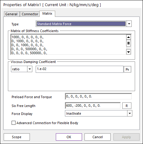
Figure 6.264 Matrix property page
The magnitude of the matrix force is calculated according to the following equations:
\(\left[ \begin{matrix} {{F}_{ax}} \\ {{F}_{ay}} \\ {{F}_{az}} \\ {{T}_{ax}} \\ {{T}_{ay}} \\ {{T}_{az}} \\ \end{matrix} \right]=-\left[ \begin{matrix} {{K}_{11}} & {{K}_{12}} & {{K}_{13}} & {{K}_{14}} & {{K}_{15}} & {{K}_{16}} \\ {{K}_{21}} & {{K}_{22}} & {{K}_{23}} & {{K}_{24}} & {{K}_{25}} & {{K}_{26}} \\ {{K}_{31}} & {{K}_{32}} & {{K}_{33}} & {{K}_{34}} & {{K}_{35}} & {{K}_{36}} \\ {{K}_{41}} & {{K}_{42}} & {{K}_{43}} & {{K}_{44}} & {{K}_{45}} & {{K}_{46}} \\ {{K}_{51}} & {{K}_{52}} & {{K}_{53}} & {{K}_{54}} & {{K}_{55}} & {{K}_{56}} \\ {{K}_{61}} & {{K}_{62}} & {{K}_{63}} & {{K}_{64}} & {{K}_{65}} & {{K}_{66}} \\ \end{matrix} \right]\left[ \begin{matrix} x-{{x}_{0}} \\ y-{{y}_{0}} \\ z-{{z}_{0}} \\ {{\theta }_{x}}-{{\theta }_{x0}} \\ {{\theta }_{y}}-{{\theta }_{y0}} \\ {{\theta }_{z}}-{{\theta }_{z0}} \\ \end{matrix} \right]-\left[ \begin{matrix} {{C}_{11}} & {{C}_{12}} & {{C}_{13}} & {{C}_{14}} & {{C}_{15}} & {{C}_{16}} \\ {{C}_{21}} & {{C}_{22}} & {{C}_{23}} & {{C}_{24}} & {{C}_{25}} & {{C}_{26}} \\ {{C}_{31}} & {{C}_{32}} & {{C}_{33}} & {{C}_{34}} & {{C}_{35}} & {{C}_{36}} \\ {{C}_{41}} & {{C}_{42}} & {{C}_{43}} & {{C}_{44}} & {{C}_{45}} & {{C}_{46}} \\ {{C}_{51}} & {{C}_{52}} & {{C}_{53}} & {{C}_{54}} & {{C}_{55}} & {{C}_{56}} \\ {{C}_{61}} & {{C}_{62}} & {{C}_{63}} & {{C}_{64}} & {{C}_{65}} & {{C}_{66}} \\ \end{matrix} \right]\left[ \begin{matrix} {{v}_{x}} \\ {{v}_{y}} \\ {{v}_{z}} \\ {{\omega }_{x}} \\ {{\omega }_{y}} \\ {{\omega }_{z}} \\ \end{matrix} \right]+\left[ \begin{matrix} {{F}_{1}} \\ {{F}_{2}} \\ {{F}_{3}} \\ {{T}_{1}} \\ {{T}_{2}} \\ {{T}_{3}} \\ \end{matrix} \right]\)
Where, the inputs into the equation are defined in the following table:
Matrix of Stiffness Coefficients |
\({{K}_{ij}}(i,j=1,2,3,4,5,6)\) |
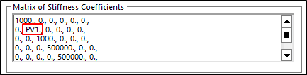
Enter the coefficient that determines spring stiffness, namely the change in the spring given a change in length (units are force/length). These values can be set by using Parametric Value. |
Viscous Damping Coefficient (matrix) |
\({{C}_{ij}}(i,j=1,2,3,4,5,6)\) |
Enter the coefficient that determines the damping force given the velocity of the spring end points (units are force-time/length). These values can be set by using Parametric Value. |
Viscous Damping Coefficient (ratio) |
The damping coefficient matrix is calculated as \(c=ratio\times K\) |
|
Pre load Force and Torque |
\({{F}_{1}},{{F}_{2}},{{F}_{3}},{{T}_{1}},{{T}_{2}},{{T}_{3}}\) |
Specify extra forces or torques in the matrix. The force and torque in the spring at its free length is the Pre-load. These values can be set by using Parametric Value. |
Six Reference Length |
\({{x}_{0}},{{y}_{0}},{{z}_{0}},{{\theta }_{x0}},{{\theta }_{y0}},{{\theta }_{z0}}\) |
Enter the lengths of the spring where it exerts no force other than the Pre-load. The default free lengths are the lengths of the spring when it is first defined. These values can be set by using Parametric Value. |
Displacements |
\(x,y,z,{{\theta }_{x}},{{\theta }_{y}},{{\theta }_{z}}\) |
Translational and rotational displacements of the action marker with respect to the base marker |
Velocities |
\({{v}_{x}},{{v}_{y}},{{v}_{z}},{{\omega }_{x}},{{\omega }_{y}},{{\omega }_{z}}\) |
Translational and rotational velocities of the action marker with respect to the base marker |
Type: Selects a type of expression as Standard Matrix Force or User Subroutine Matrix Force.
Standard Matrix Force: Defines a standard matrix force by using the function expression.
User Subroutine Matrix Force: Defines a user subroutine matrix force by using the user subroutine. Refer to Matrix Force USUB.
Force Display: Displays the resultant force vector graphically on Working Window.
Advanced Connection for Flexible Body: If user selects this option, the bushing force is directly connected two body not using virtual body connection. If there’s no flexible body (RFlex or FFlex), this option is ignored.
Note
The user can use Parametric Value in Matrix of Stiffness Coefficient, Viscous Damping Coefficient (matrix), Preload Force and Torque, and Six Reference Length.