40.2.2.4. Nonlinear Characteristic of spring (axial force)
To check the properties of axial force, Click right mouse button on an Axial force entity in database window.
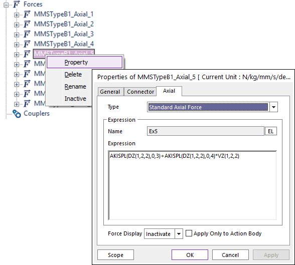
Figure 40.21 Properties of an Axial force
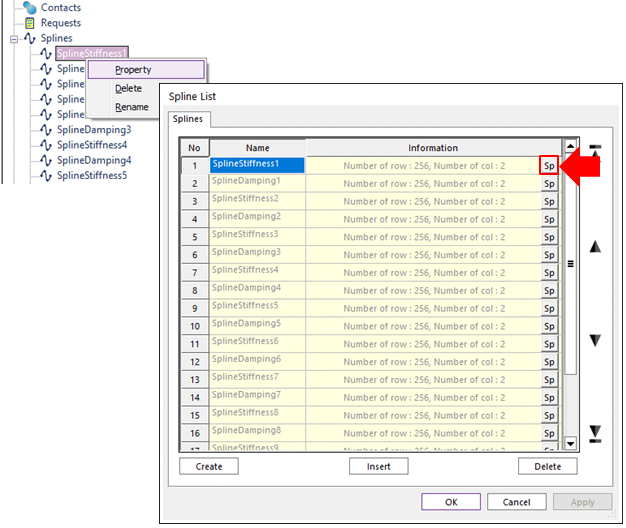
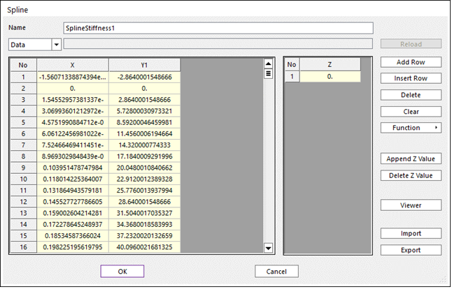
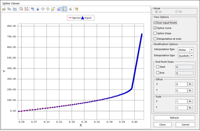
Figure 40.22 Properties of spline
Note
Calculation of the axial segment positions. In general within the BMW_MMS spring approach the axial segment body locations do not influence the spring characteristics because all necessary stiffness and damping characteristics of the spring (including coil clash situations) are stored in the segment splines which are generated during the static compression pre-calculation based on a very fine spring discretization. Since all segment splines start from the undeformed length (i.e. 0.0,0.0) theoretically all segment bodies could be located at the First Point position if the markers used in the AKISPL function expression of the segment forces are located in accordance to that. As a conclusion the axial segment body distribution is for visualization purposes only.
For a given number of Number of Segments, Number of Segments +1 bodies are generated which comprise Number of Segments connecting forces. First the segment body positions of the undeformed spring are calculated as a function of the z – coordinate (“Height” column) of the skeleton profile information. Those locations can be found in the spring generation log file under the “Definition points for geometric visualization” information block. The undeformed positions for segment 1 to Number of Segments +1 are displayed in the “z(for L0)” column for the appropriate “PointNo” which is related to the segment body number. The entries for PointNo. 000 and PointNo. Number of Segments +2 are taken from the skeleton profile information table and are the first, respectively last entries in the “Height” column. Note that the distribution of segment body locations for L0 is NOT influenced by the Free Length value because the skeleton profile information has primary character compared to the user entered Free Length value.
If the value for Installed Length differs from the Free Length value the actual distribution of the segment body axial locations are calculated from the static compression pre-calculation by adding the local segment displacements for the Installed Length to the original L0 values. The calculated segment body positions for L1 are displayed in the spring generation log file under the “Definition points for geometric visualization” information block in the “z (for L1)” column. The segment body displacements (column “004” to column “Number of Segments +5”) for a given spring length (column “002”) can be found in the “Results of MMS” information block. At least the dynamic shell graphic of the spring is compressed from the L0 shape to the L1 shape by interpolation
Note
Calculation of the segment mass distribution. The mass values for the internal segments (segment #2 thru segment # Number of Segments-1) are approximated by the following formula:
\(Segment\_mass=\frac{Total\ Mass\cdot \frac{Max\_Angle-Inactive\ Coil\cdot 360}{Max\_Angle}}{Number\ of\ Segment-1}\)
Max_Angle is the maximum value of the “Phi(Deg)” column of the skeleton profile information table. The masses of the first and the last segment bodies are calculated by
\(mass=\frac{Total\ Mass-\left( Number\ of\ Segment-1 \right)\cdot Segment\_mass}{2}\)