31.1.12. Gear Dog
Gear dog is used transmit torque to another gear. It is mainly used for dog clutch mechanism in gear box. When user creates Gear Dogs to gear geometry, fixed joints are also created and connect Gear dogs and gear geometry. Gear Dogs can be attached to Spur Gear, Helical Gear, QFB Gear, Scissors Gear in RecurDyn/Gear.
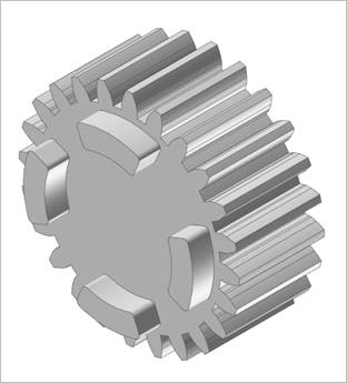
Figure 31.65 Spur Gear & Gear Dog
31.1.12.1. Modeling Options
Body(Group), WithDialog, WithDialog
Body(Group): Selects a gear body created in RecurDyn.
WithDialog: The Gear Dog Type dialog is shown. After setting, the next dialog appears with clicking Next.
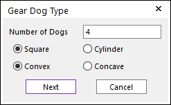
Figure 31.66 Gear Dog Type dialog box
Number of Dogs: Enters the number of dogs. The maximum number of dogs is 10
Square/Cylinder: Select the geometry type of dogs. Square type uses Inner Edge Radius and Outer Edge Radius to determine the edge shape. Cylinder type uses Pitch Circle Diameter, Front Radius and Rear Radius to determine the edge shape.
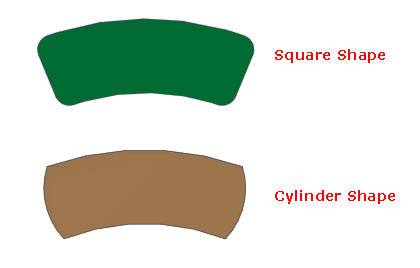
Figure 31.67 Shapes
Convex/Concave: Select the attached direction of gear dogs. If Convex is selected, gear dogs are attached to outward side of the gear. If Concave is selected, gear dogs are attached to inward side of the gear.
WithDialog: Gear Dog dialog box is shown. After setting geometry data, the gear dog is created by clicking OK.
Point, Point, Radius, WithDialog, WithDialog
Point: Selects a point to define an end surface of the gear web geometry.
Point: Selects a point to define another end surface of the gear web geometry.
Radius: Selects a radius of the gear web geometry.
WithDialog: The Gear Dog Type dialog is shown. After setting, the next dialog appears with clicking Next.
WithDialog: Gear Dog dialog box is shown. After setting geometry data, the gear dog is created by clicking OK.
31.1.12.2. Properties
The Gear Dog property page is shown as the below. The parameters are explained below.
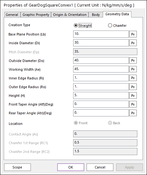
Figure 31.68 Gear Dog property page [Square shape]
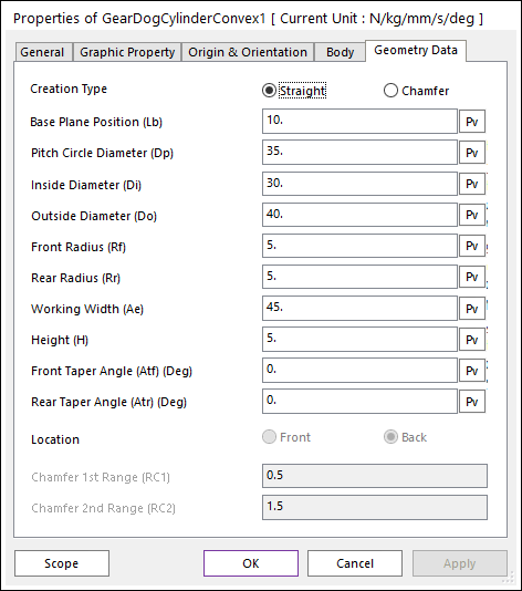
Figure 31.69 Gear Dog property page [Cylinder shape]
Creation Type: Selects a type for the gear dog. The default shape is Straight type. If Chamfer is selected, chamfer operation is applied on the gear dog geometry.
Base Plane Position (Lb): Enters the base plane position from the center of the gear measured parallel to its axis.
Pitch Circle Diameter (Dp): Enters the pitch circle diameter. Arc center from side of gear dog is located on the circle from center with its diameter.
Inside Diameter (Di): Enters the diameter of circle from the inner side of the gear dog.
Outside Diameter (Do): Enters the diameter of circle from the outer side of the gear dog.
Front Radius (Rf): Enters the front radius. It is arc length of one side of gear dog.
Rear Radius (Rr): Enters the rear radius. It is arc length of another side of gear dog.
Working Width (Ae): Enters the angle between each sides of gear dog with respect to axis of the gear.
Height (H): Enters the height of the gear dog.
Front Taper Angle (Atf): Enters the front taper angle.
Rear Taper Angle (Atr): Enters the rear taper angle.
Inner Edge Radius (Ri): Enters the inner diameter of circle from the edge close to the axis of the gear.
Outer Edge Radius (Ri): Enters the outer diameter of circle from the edge far from the axis of the gear.
Location: Select the side where the gear dog is attached.
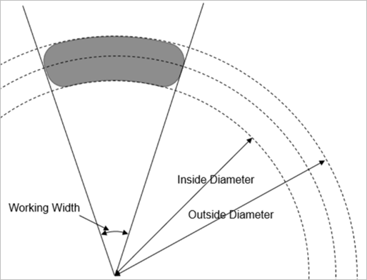
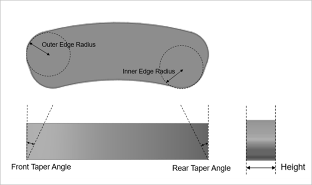
Figure 31.70 Gear Dog terminology
Chamfer: It allow the users to create narrow flat surfaces along the edges of the gear dog.
Contact Angle (Ac): It is used to change the working width only for the side of gear dog while maintaining the overall length. Unit is degree.
Chamfer 1st Range (RC1): Specifies the cutting depth of chamfer with respect to the original geometry.
Chamfer 2nd Range (RC2): Specifies the cutting depth of chamfer with respect to the original geometry.
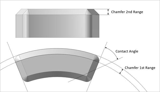
Figure 31.71 Gear Dog Chamfer Terminology