30.2.10. Lateral Guard
A lateral guard geometry is defined by two box geometric entities. (The width and depth of the lateral guard must be large enough to contact with the chain link pin.)
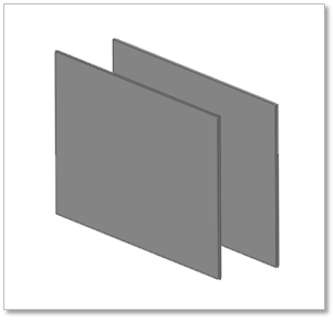
Figure 30.72 Lateral guard geometry
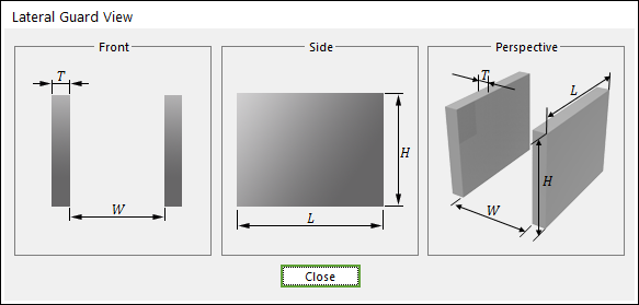
Figure 30.73 Lateral guard dimension information
L |
Length |
H |
Height |
W |
Inner Width |
T |
Thickness |
30.2.10.1. Modeling Options
The user can create a lateral guard as follows.
Point, Point
Point: Selects a point to define the one corner of the lateral guard.
Point: Selects a point to define the opposite corner of the lateral guard.
30.2.10.2. Properties
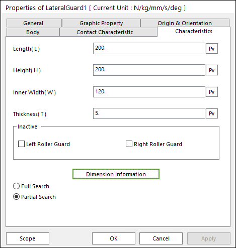
Figure 30.74 Lateral Guard property page [Characteristics page]
The Lateral Guard property page is shown in Figure 30.74. The parameters are explained below. In order to understand the geometry, refer to Dimension Information.
Length(L): Enters the length of guard.
Height(H): Enters the height of guard.
Inner Width(W): Enters the width between guards.
Thickness(T): Enters the thickness of guard.
Inactive: The checked guard can be inactive.
Left Roller Guard: This is a left lateral guard.
Right Roller Guard: This is a right lateral guard.
Note
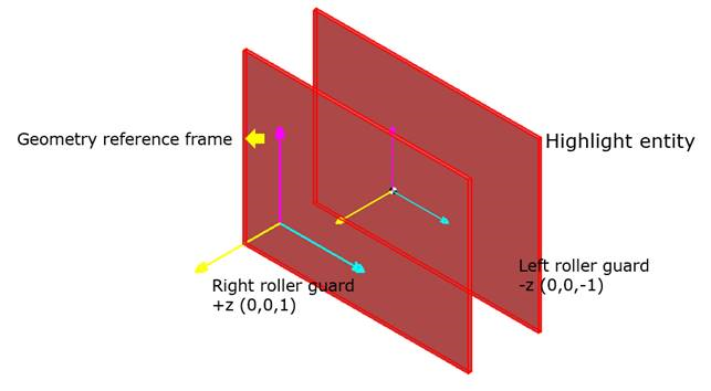
Figure 30.75 Direction of right and left roller guard
Full Search: All links are searched for contact.
Partial Search: Some links are searched for contact in some boundary. It is used to reduce total solving time.
30.2.10.2.1. Contact between a Lateral Guard and a Link
The lateral guard is in contacts with the chain link in the one part.
The side surface of chain link pin - the inner surface of lateral guard.
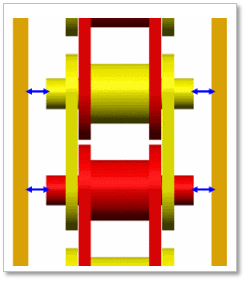
Figure 30.76 Contact between lateral guard and chain links