32.2.8. Balancing Shaft
A balancing shaft is a group, which is composed of a balancing shaft body and a balancing shaft weight. The balancing shaft is connected with a crankshaft by a balancing screw coupler. And the balancing shaft weight is connected with the balancing shaft body by a fixed joint.
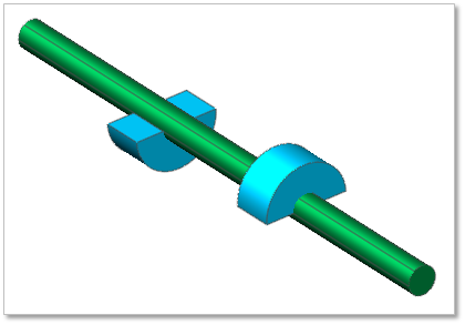
Figure 32.89 Balancing Shaft
Terminology
Reference Parametric Marker
Length of Balancing shaft body
Diameter of Balancing shaft body
Axial Distance of Balancing shaft weight
Radial Distance of Balancing shaft weight
Angle of Balancing shaft weight
Diameter of Balancing shaft weight
32.2.8.1. Modeling Options
Click the Bal.Shaft icon of the Crank group in the Crank tab. The user can see the Crank Component – BalancingShaft dialog box.
The user can select the position where a balancing shaft is created in Component Index. The maximum number of Balancing shaft can be created is 2.
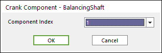
Figure 32.90 Crank Component - BalancingShaft dialog box
Click OK.
32.2.8.2. Properties
Click the right mouse button on the balance shaft body to choose Properties of balance shaft. The user can modify the property of balancing shaft in the following dialog.
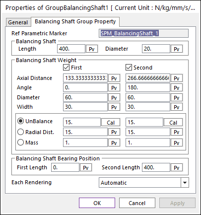
Figure 32.91 Balancing Shaft property page
Reference Parametric Marker: Controls the position of balancing shaft. It is also a special parametric marker.
Length and Diameter of balancing shaft: Control the shape of balancing shaft body.
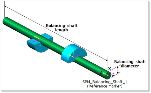
Figure 32.92 Geometrical Information of Balancing shaft
Balancing Shaft weight: Can be created up to 2per 1 balancing shaft. Axial Distance, Radial Distance and Angle are parameters to determine the position of Balancing Shaft Weight. Balancing Shaft Weight Radius/Width controls the shape of balancing shaft weight.
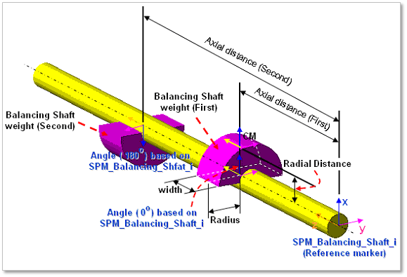
Figure 32.93 Geometrical information of balancing shaft weight
Unbalancing value
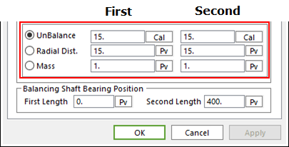
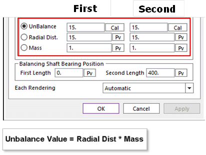
Figure 32.94 Unbalancing value
An example in above dialog(a)
Select the option of Unbalancing,
Change the values of Radial Dist and Mass as follow.
And then click Cal to get the new Unbalancing value.
Balancing shaft Bearing Position
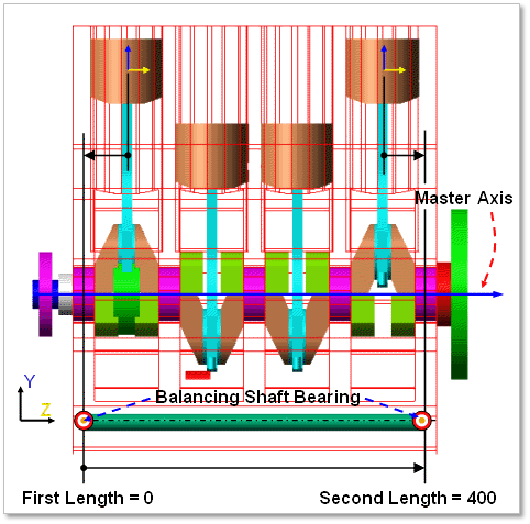
Figure 32.95 Balancing Shaft Bearing Position
Each Rendering: The selected mode can be displayed in Each Render mode.