6.2.3.6. Perpendicular
A perpendicular joint constraints the z-axis of action marker to be perpendicular to the z-axis of the base marker as shown in Figure 6.216. The marker of the action body can be rotated about two axes with respect to the base body.
The resulting degrees of freedom are five. The rotation degrees of freedom are two and the translational degrees of freedom are three.
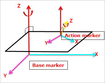
Figure 6.216 Definition of Perpendicular Joint
6.2.3.6.1. Modeling Options
The user can create a joint entity as follows.
Point, Direction, Direction
Point: Selects a point on two bodies to define the location of the perpendicular joint.
Direction: Defines the z-axis of the base marker.
Direction: Defines the z-axis of the action marker, which should be perpendicular to the z-axis of the base marker.
Point, Point, Direction, Direction
Point: Selects a point on a base body.
Point: Selects a point on an action body.
Direction: Defines the z-axis of the base marker.
Direction: Defines the z-axis of the action marker, which should be perpendicular to the z-axis of the base marker.
Body, Body, Point, Direction, Direction
Body: Selects a base body of the perpendicular joint.
Body: Selects an action body of the perpendicular joint.
Point: Selects a point to define the location of the perpendicular joint.
Direction: Defines the z-axis of the base marker.
Direction: Defines the z-axis of the action marker, which should be perpendicular to the z-axis of the base marker.
Body, Body, Point, Point, Direction, Direction
Body: Selects a base body of the perpendicular joint.
Body: Selects an action body of the perpendicular joint.
Point: Selects a point on a base body.
Point: Selects a point on an action body.
Direction: Defines the z-axis of the base marker.
Direction: Defines the z-axis of the action marker, which should be perpendicular to the z-axis of the base marker.
6.2.3.6.2. Properties
The user can only define the force display using the Joint page.
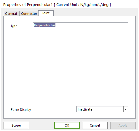
Figure 6.217 Perpendicular property page [Joint page]
Type: Shows the type of joint.
Force Display: Displays the resultant force vector graphically on Working Window.