6.4.2.7. Sphere To Surface
A Sphere To Surface Contact generates a force between one surface and the other sphere.
The sphere and the surface must belong to two different bodies.
The contact force can be not only linear or exponential but also nonlinear spline characteristics to the contact penetration and its velocity.
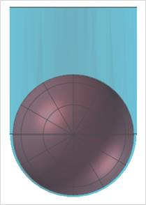
The base surface is approximated as multi triangular patches as shown in Figure 6.346.
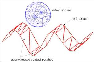
Figure 6.346 Approximated base contact surface
6.4.2.7.1. Modeling Options
In the case of Sphere To Surface contact, a sphere geometry type is supported for an action geometry and surface geometry type is supported for a base geometry when creating.
Surface, Sphere
Surface: Selects a surface to define a base surface.
Sphere: Selects a sphere to define an action sphere.
Surface, MultiSphere
Surface: Selects a surface to define a base surface.
MultiSphere: Selects some spheres to define action spheres.
Surface, Sphere, Surface, Sphere
Surface: Selects a surface to define a base surface.
Sphere: Selects a sphere to define an action sphere.
Surface: Selects a surface to define another base surface.
Sphere: Selects a sphere to define another action sphere.
MultiSurface, MultiSphere
MultiSurface: Selects some surfaces to define base surfaces.
MultiSphere: Selects some spheres to define action spheres.
6.4.2.7.2. Properties
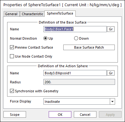
Figure 6.347 Properties of SphereToSurface dialog box
Definition of The Base Surface
Entity Name: Defines the name of base surface. The base surface can be dispatched from the Working Window by clicking Gr.
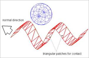
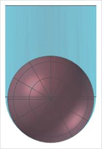
Figure 6.348 Preview of the normal direction and contact patches
Normal Direction: Defines the normal direction of a base surface for a contact as shown in Figure 6.348.
The contact is available in the specified direction.
As selecting Up or Down, the user can change the contact direction of a base surface.
If this page is activated, the normal direction is automatically shown on the Working Window
Preview Contact Surface: If this option is checked, the patches making the contact surface are shown on the Working Window.
Base Surface Patch: Accesses the Base Surface Patch dialog box as shown in Figure 6.349.
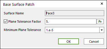
Figure 6.349 Base Surface Patch dialog box
Plane Tolerance Factor: Specifies the surface tolerance factor as a value from 0 to 10. A smaller value produces a more refined patch. For more information, click here.
Minimum Plane Tolerance: While using extended surface to surface contact, to make refined patch, decrease plane tolerance factor. If the decreasing plane tolerance factor has no effect on patch, decrease minimum plane tolerance. For very small geometries such as 1mm * 1mm size, maybe they need to decrease minimum plane tolerance to get effective patch. The default value of minimum plane tolerance is 1.e-5.
Use Node Contact Only: Nodes of contact surface are used to generate the contact force of sphere to surface contact. Generally, this option can be very useful for accuracy and solving speed when the triangular patch size ( or line length of triangular patch ) is much smaller than sphere size (or radius).
If the user does not use this option, the contact is applied as patch shape only.
If the user uses this option, the contact is applied as flexible body shape more correctly.
Definition of The Action Sphere
Entity Name: Defines the name of action sphere. The action sphere can be dispatched from the Working Window by clicking Gr.
Radius: Shows the radius of base sphere. This value is automatically determined by the radius of the action geometry but if the user doesn’t check the Synchronize with Geometry option, the user can directly input the radius or change it as the parametric value by clicking PV.
Synchronize with Geometry
If this option is checked, Radius in contact properties is automatically defined with that of the specified graphic.
If this option is not checked, the user can modify the contact properties.
Force Display: Graphically displays the resultant force vector on the view window.