19.2.2.1. Bearing
There are many bearing components in the transmission system. User can create various types of bearing components connected to shaft and housing in this function.
19.2.2.1.1. Modeling Options
The user can create a bearing force as follows.
Point, WithDialog
Point: Specify points to make bearing inner and outer body.
WithDialog: Modifies the property list for the bearing. The bearing is created with clicking OK.
Point, Direction, WithDialog
Point: Specify points to make bearing inner and outer body.
Direction: Specify bearing axial direction. (Default is 0,0,1)
WithDialog: Modifies the property list for the bearing. The bearing is created with clicking OK.
19.2.2.1.2. Properties
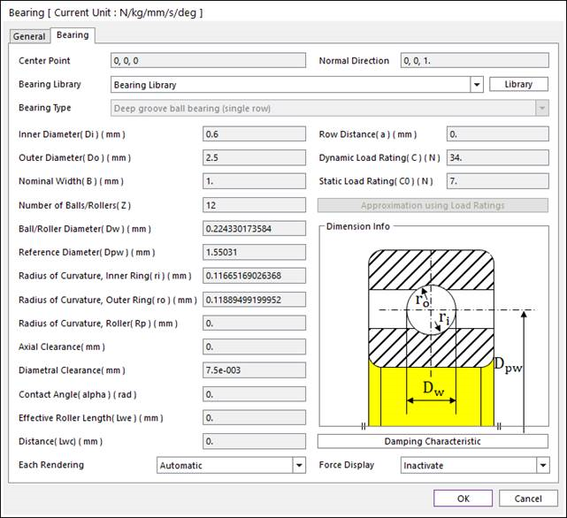
Figure 19.11 Properties of Bearing Group dialog box
Center Point: Specify the center point of bearing group.
Normal Direction: Specify the normal direction of bearing group.
Bearing Library: User can define bearing properties by direct input or selecting bearing data base KISSsoft provide. If Bearing Library is selected, bearing properties below are defined automatically according to bearing library data. If User Input is selected, user has to set bearing type first. And then, input the bearing properties according to the bearing type.
Note
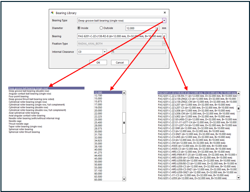
Figure 19.12 Bearing Library
Diameter: Select inside or outside diameter to classify bearings with this diameter condition.
Bearing: Select a bearing that satisfies diameter condition from bearing list. If the label of the bearing has a “*. after the bracket (e.g. SKF 6008 (…) *), this means that the database contains at least one internal geometry value.
Fixation Type: Display bearing fixation type set for each bearing type in order to reflect real bearing geometry. 7 fixation types are available (RADIAL_ONLY, RADIAL_AXIAL_BOTH, RADIAL_AXIAL_RIGHT, RADIAL_AXIAL_LEFT, AXIAL_ONLY_BOTH, AXIAL_ONLY_RIGHT, AXIAL_ONLY_LEFT).
RADIAL_ONLY: Bearing force reacts to radial displacement only.
RADIAL_AXIAL_BOTH: Bearing force reacts to radial and axial displacement (is fixed axially in both directions).
RADIAL_AXIAL_RIGHT: Bearing force reacts to radial and axial displacement (is fixed axially in +Z direction).
RADIAL_AXIAL_LEFT: Bearing force reacts to radial and axial displacement (is fixed axially in -Z direction).
AXIAL_ONLY_BOTH: Bearing force reacts to axial displacement only (in both directions).
AXIAL_ONLY_RIGHT: Bearing force reacts to axial displacement only (is fixed in +Z direction).
AXIAL_ONLY_LEFT: Bearing force reacts to axial displacement only (is fixed in -Z direction).
In the case of cylindrical roller bearings, user should select proper fixation type because fixation type depends on ths subtype of it. Please refer to this information.
Following subtypes of cylindrical roller bearing can accomadate bearing force react to radial displacement only.
Single row: N, NU, NUB, RN, RNU
Double row: NN, NNU, NNUB, NNCL
Following subtypes of cylindrical roller bearing can accomadate bearing force react to radial and axial displacement (+Z or -Z axial fixation possible).
Single row: NJ, NF, NJP, NCF, NJG
Double row: NNCF
Following subtypes of cylindrical roller bearing can accomadate bearing force react to radial and axial displacement (both axial fixation possible).
Single row: NP, NUP
Double row: NNUP, NNC, NNF
Internal Clearance: Specify bearing internal clearance.
Note
If the bearing inner geometry is provided by the manufacturer, then it is used in the calculation. If it is unknown, then KISSsoft runs an approximation method that uses the bearing load ratings (both static C0 and dynamic C) provided by the manufacturer to calculate the internal geometry. This procedure is based on ISO 76 and ISO 281-4 and generates very useful results in general. For more information about the bearing internal geometry, please refer to KISSsoft manual Rolling bearing calculation with internal geometry.
Bearing Type: Select bearing type If User input is defined in Bearing Library. RecurDyn supports 17 bearing types from KISSsoft.
Inner Diameter(Di): Inner diameter of the ball in the case of ball bearing.
Outer Diameter(Do): Outer diameter of the ball In the case of ball bearing.
Normal Width(B): Bearing width.
Number of Balls/Rollers(Z): Number of rolling elements.
Ball/Roller Diameter(Dw): Diameter of the rolling element(ball/roller).
Reference Diameter(Dpw): Pitch diameter of the rolling elements.
Radius of Curvature, Inner Ring(ri): Raceway radius – inner(bearing dependent).
Radius of Curvature, Outer Ring(ro): Raceway radius – outer(bearing dependent).
Radius of Curvature, Roller(Rp): (Only for spherical bearings –axial,radial) Roller radius
Axial Clearance: Axial clearance of the bearing. It is the total amount of free axial motion between a bearing’s inner and outer race.
Diametral Clearance: Diametral clearance of the bearing. It is the gap in a fixed outer ring between the upper and the lower position the inner ring can have without load.
Contact Angle(alpha): Pressure angle. It is defined as the angle between the line that joins the ball contact points and the raceways in the radial plane along which the combined load is transmitted from one raceway to another, and a line that is perpendicular to the bearing axis.
Effective Roller Length(Lwe): Roller length.
Distance(Lwc): (Only for spherical bearings -axial) distance
Row Distance(a): (Only for double row cylindrical) roller center line distance.
Dynamic Load Rating(C): Dynamic load rating.
Static Load Rating(C0): Static load rating.
Approximation using Load Ratings: When the selected bearing does not have inner geometry information, KISSsoft can calculate approximated internal geometry. If the users know more exact information, the user can modify and apply that.
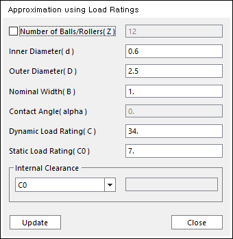
Figure 19.13 Approximated Load Ratings dialog box
Damping Characteristic: RD automatically calculate damping force using damping ratio and damping stiffness exponent with stiffness by bearing force. The relationship is as follows:
\(\mathbf{C}=\zeta \mathbf{K}^n\)
\(\mathbf{f}_d=\mathbf{C}\dot{x}\)
- where,
- \(\zeta\) :Damping coefficient\(n\): Damping exponent\(\mathbf{C}\): Damping matrix\(\mathbf{K}\): Stiffness matrix\(\dot{x}\): RElative velocity between action and base marker\(\mathbf{f}_d\): Force by damping effect
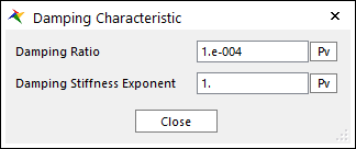
Figure 19.14 Damping Characteristic dialog box
Damping Ratio: Propornational damping coefficient to the bearing stiffness.
Damping Stiffness Exponent: Damping exponent to the bearing stiffness.
19.2.2.1.3. Specialized Outputs
KISSsoft Bearing has specialized outputs.
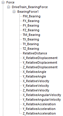
Figure 19.15 RPLT Data of KISSsoft Bearing.
RelativeDistance: Distance between action and base marker.
X_RelativeDisplacement: DX of action marker with respect to base marker
Y_RelativeDisplacement: DY of action marker with respect to base marker
Z_RelativeDisplacement: DZ of action marker with respect to base marker
X_RelativeAngle: Roll of action marker with respect to base marker
Y_RelativeAngle: Pitch of action marker with respect to base marker
X_RelativeVelocity: VX of action marker with respect to base marker
Y_RelativeVelocity: VY of action marker with respect to base marker
Z_RelativeVelocity: VZ of action marker with respect to base marker
X_RelativeAngularVelocity: WX of action marker with respect to base marker
Y_RelativeAngularVelocity: WY of action marker with respect to base marker
X_RelativeAcceleration: ACCX of action marker with respect to base marker
Y_RelativeAcceleration: ACCY of action marker with respect to base marker
Z_RelativeAcceleration: ACCZ of action marker with respect to base marker
Note
There are cases where the direction of the reaction force is limited according to the bearing type. In the case of angular contact ball bearing (single row), taper rolling bearing (single row), spherical roller thrust bearing and axial angular contact roller bearing, the reaction force in the +z direction does not occur. In the case of needle cage bearing, cylindrical rollere bearing (single row), cylindrical rollere bearing (double row), cylindrical rollere bearing (single row, full complement) and cylindrical rollere bearing (double row, full complement), the reaction force in the axial direction does not occur. In the case of thrust needle cage bearing, the reaction force in the radial direction does not occur.