4.7.1.3.1. Displacement
A marker in { } is optional. If the user does not define optional markers, those markers use Ground.InertiaMarker. The user can define a marker name as follows:
(m1,{m2},{m3}) : (bodyname.markername, {bodyname.markername}, {bodyname.markername}).
m1 becomes action marker.
If m2 is defined, m2 becomes base marker.
If m3 is defined, m3 becomes reference marker.
4.7.1.3.1.1. DM
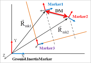
The DM function returns the absolute distance from one marker to the Ground.InertiaMarker or the absolute distance between two markers.
Format
DM(Marker1{, Marker2})
Arguments definition
Marker1 |
The name or argument number of a marker to be calculated |
Marker2 |
|
Formulation
\(\text{DM}={{\left( \left[ {{{\vec{R}}}_{\text{mk1}}}-{{{\vec{R}}}_{\text{mk2}}} \right]\cdot \left[ {{{\vec{R}}}_{\text{mk1}}}-{{{\vec{R}}}_{\text{mk2}}} \right]\, \right)}^{1/2}}\)
\({{\vec{R}}_{\text{mk1}}}\): Position vector of Marker1
\({{\vec{R}}_{\text{mk2}}}\): Position vector of Marker2
Example
4.7.1.3.1.2. DX
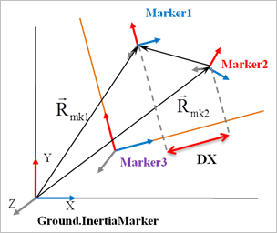
The DX function returns the x-direction location of one marker or the distance between two markers in relation to a third marker’s x-direction.
Format
DX(Marker1{, Marker2}{, Marker3})
Arguments definition
Marker1 |
The name or argument number of a marker to be calculated |
Marker2 |
|
Marker3 |
|
Formulation
\(\text{DX}=\left[ {{{\vec{R}}}_{\text{mk1}}}-{{{\vec{R}}}_{\text{mk2}}} \right]\,\cdot \,{{\hat{x}}_{\text{mk3}}}\)
\({{\vec{R}}_{\text{mk1}}}\): Position vector of Marker1
\({{\vec{R}}_{\text{mk2}}}\): Position vector of Marker2
\({{\hat{x}}_{\text{mk3}}}\): x-direction unit vector of Marker3
Example
4.7.1.3.1.3. DY
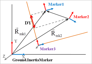
The DY function returns the y-direction location of one marker or the distance between two markers in relation to a third marker’s y-direction.
Format
DY(Marker1{, Marker2}{, Marker3})
Arguments definition
Marker1 |
The name or argument number of a marker to be calculated |
Marker2 |
|
Marker3 |
|
Formulation
\(\text{DY}=\left[ {{{\vec{R}}}_{\text{mk1}}}-{{{\vec{R}}}_{\text{mk2}}} \right]\,\cdot {{\hat{y}}_{\text{mk3}}}\)
\({{\vec{R}}_{\text{mk1}}}\): Position vector of Marker1
\({{\vec{R}}_{\text{mk2}}}\): Position vector of Marker2
\({{\hat{y}}_{\text{mk3}}}\): y-direction unit vector of Marker3
Example
4.7.1.3.1.4. DZ
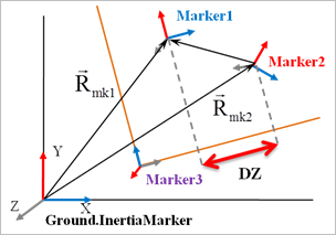
The DZ function returns the z-direction location of one marker or the distance between two markers in relation to a third marker’s z-direction.
Format
DZ(Marker1{, Marker2}{, Marker3})
Arguments definition
Marker1 |
The name or argument number of a marker to be calculated |
Marker2 |
|
Marker3 |
|
Formulation
\(\text{DZ}=\left[ {{{\vec{R}}}_{\text{mk1}}}-{{{\vec{R}}}_{\text{mk2}}} \right]\,\cdot \,{{\hat{z}}_{\text{mk3}}}\)
\({{\vec{R}}_{\text{mk1}}}\): Position vector of Marker1
\({{\vec{R}}_{\text{mk2}}}\): Position vector of Marker2
\({{\hat{z}}_{\text{mk3}}}\): z-direction unit vector of Marker3
Example
4.7.1.3.1.5. AX
The AX function returns the cumulative rotation angle on the x-axis for one marker’s InertiaMarker or the cumulative rotation angle on the x-axis for two markers.
Format
AX(Marker1{, Marker2})
Arguments definition
Marker1 |
The name or argument number of a marker to be calculated |
Marker2 |
|
Formulation
\(\text{AX}=ATAN2(-{{\hat{z}}_{\text{mk1}}}\cdot {{\hat{y}}_{\text{mk2}}},{{\hat{z}}_{\text{mk1}}}\cdot {{\hat{z}}_{\text{mk2}}})\)
\({{\hat{y}}_{\text{mk2}}}\): y-direction unit vector of Marker2
\({{\hat{z}}_{\text{mk1}}}\): z-direction unit vector of Marker1
\({{\hat{z}}_{\text{mk2}}}\): z-direction unit vector of Marker2
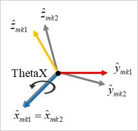
Here, ThetaX is utilized to calculate the cumulative rotation angle on the x-axis for two markers.
If x-axis for two markers is deviated, ThetaX becomes inaccurate result.
Example
4.7.1.3.1.6. AY
The AY function returns the cumulative rotation angle on the y-axis for one marker’s InertiaMarker or the cumulative rotation angle on the y-axis for two markers.
Format
AY(Marker1{, Marker2})
Arguments definition
Marker1 |
The name or argument number of a marker to be calculated |
Marker2 |
|
Formulation
\(\text{AY}=ATAN2({{\hat{z}}_{\text{mk1}}}\cdot {{\hat{x}}_{\text{mk2}}},{{\hat{z}}_{\text{mk1}}}\cdot {{\hat{z}}_{\text{mk2}}})\)
\({{\hat{z}}_{\text{mk1}}}\): z-direction unit vector of Marker1
\({{\hat{x}}_{\text{mk2}}}\): x-direction unit vector of Marker2
\({{\hat{z}}_{\text{mk2}}}\): z-direction unit vector of Marker2
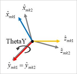
Here, ThetaY is utilized to calculate the cumulative rotation angle on the y-axis for two markers.
If y-axis for two markers is deviated, ThetaY becomes inaccurate result.
Example
4.7.1.3.1.7. AZ
The AZ function returns the cumulative rotation angle on the z-axis for one marker’s InertiaMarker or the cumulative rotation angle on the z-axis for two markers.
Format
AZ(Marker1{, Marker2})
Arguments definition
Marker1 |
The name or argument number of a marker to be calculated |
Marker2 |
|
Formulation
\(\text{AZ}=ATAN2({{\hat{x}}_{\text{mk1}}}\cdot {{\hat{y}}_{\text{mk2}}},{{\hat{x}}_{\text{mk1}}}\cdot {{\hat{x}}_{\text{mk2}}})\)
\({{\hat{x}}_{\text{mk1}}}\): x-direction unit vector of Marker1
\({{\hat{y}}_{\text{mk2}}}\): y-direction unit vector of Marker2
\({{\hat{x}}_{\text{mk2}}}\): x-direction unit vector of Marker2
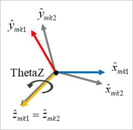
Here, ThetaZ is utilized to calculate the cumulative rotation angle on the z-axis for two markers.
If z-axis for two markers is deviated, ThetaZ becomes inaccurate result.
Example
Note
The result of ATAN2 as FORTRAN function lies in the range -PI~PI. However, the AX, AY and AZ as expression functions always return an accumulated angle along a rotating direction. The accumulated angle is growing or decaying with the growing time. If the user wants to get a wrapped value by a special angle, use the function expression, MOD’. Please refer to the following Example.

Figure 4.40 Example of using the AZ function
If the user wants to get the result lies in range 0 ~ 360 degree.
MOD(AZ(m1,m2),360d) (radian)
MOD(AZ(m1,m2),360d)*RTOD (deg)
- If the user wants to get the result lies in range -180 ~ 180 degree.
MOD(AZ(m1,m2),360d)-PI (radian)
(MOD(AZ(m1,m2),360d)-PI)*RTOD (deg)
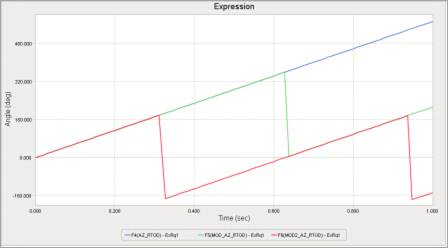
Figure 4.41 Results of expressions
4.7.1.3.1.8. PSI
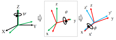
The PSI function returns the rotation angle of the first rotation in a z-x-z sequence of Euler angles.
Format
PSI(Marker1{, Marker2})
Arguments definition
Marker1 |
The name or argument number of a marker to be calculated |
Marker2 |
|
Formulation
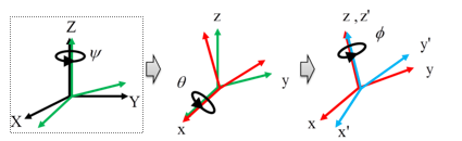
\(\left[ \begin{matrix} \text{X} \\ \text{Y} \\ \text{Z} \\ \end{matrix} \right]=\left[ \begin{matrix} \cos \text{ }\psi & -\sin \text{ }\psi & 0 \\ \sin \text{ }\psi & \cos \text{ }\psi & 0 \\ 0 & 0 & 1 \\ \end{matrix} \right]\left[ \begin{matrix} 1 & 0 & 0 \\ 0 & \cos \text{ }\theta & -\sin \text{ }\theta \\ 0 & \sin \text{ }\theta & \cos \text{ }\theta \\ \end{matrix} \right]\left[ \begin{matrix} \cos \text{ }\phi & -\sin \text{ }\phi & 0 \\ \sin \text{ }\phi & \cos \text{ }\phi & 0 \\ 0 & 0 & 1 \\ \end{matrix} \right]\left[ \begin{matrix} \text{x }\!\!'\!\!\text{ } \\ \text{y }\!\!'\!\!\text{ } \\ \text{z }\!\!'\!\!\text{ } \\ \end{matrix} \right]\)
In line with the sequentially defined rotation order, return rotation angle \(\mathrm{ }\!\!\psi\!\!\text{ }\) on the z-axis, which is the first rotation.
Example
4.7.1.3.1.9. THETA
The THETA function returns the rotation angle of the second rotation in a z-x-z sequence of Euler angles.
Format
THETA(Marker1{, Marker2})
Arguments definition
Marker1 |
The name or argument number of a marker to be calculated |
Marker2 |
|
Formulation
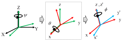
\(\left[ \begin{matrix} \text{X} \\ \text{Y} \\ \text{Z} \\ \end{matrix} \right]=\left[ \begin{matrix} \cos \text{ }\psi & -\sin \text{ }\psi & 0 \\ \sin \text{ }\psi & \cos \text{ }\psi & 0 \\ 0 & 0 & 1 \\ \end{matrix} \right]\left[ \begin{matrix} 1 & 0 & 0 \\ 0 & \cos \text{ }\theta & -\sin \text{ }\theta \\ 0 & \sin \text{ }\theta & \cos \text{ }\theta \\ \end{matrix} \right]\left[ \begin{matrix} \cos \text{ }\phi & -\sin \text{ }\phi & 0 \\ \sin \text{ }\phi & \cos \text{ }\phi & 0 \\ 0 & 0 & 1 \\ \end{matrix} \right]\left[ \begin{matrix} \text{x }\!\!'\!\!\text{ } \\ \text{y }\!\!'\!\!\text{ } \\ \text{z }\!\!'\!\!\text{ } \\ \end{matrix} \right]\)
In line with the sequentially defined rotation order, return rotation angle θ on the x-axis, which is the second rotation.
Example
4.7.1.3.1.10. PHI
The PHI function returns the rotation angle of the third rotation in a z-x-z sequence of Euler angles.
Format
PHI(Marker1{, Marker2})
Arguments definition
Marker1 |
The name or argument number of a marker to be calculated |
Marker2 |
|
Formulation
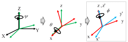
\(\left[ \begin{matrix} \text{X} \\ \text{Y} \\ \text{Z} \\ \end{matrix} \right]=\left[ \begin{matrix} \cos \text{ }\psi & -\sin \text{ }\psi & 0 \\ \sin \text{ }\psi & \cos \text{ }\psi & 0 \\ 0 & 0 & 1 \\ \end{matrix} \right]\left[ \begin{matrix} 1 & 0 & 0 \\ 0 & \cos \text{ }\theta & -\sin \text{ }\theta \\ 0 & \sin \text{ }\theta & \cos \text{ }\theta \\ \end{matrix} \right]\left[ \begin{matrix} \cos \text{ }\phi & -\sin \text{ }\phi & 0 \\ \sin \text{ }\phi & \cos \text{ }\phi & 0 \\ 0 & 0 & 1 \\ \end{matrix} \right]\left[ \begin{matrix} \text{x }\!\!'\!\!\text{ } \\ \text{y }\!\!'\!\!\text{ } \\ \text{z }\!\!'\!\!\text{ } \\ \end{matrix} \right]\)
In line with the sequentially defined rotation order, return rotation angle φ on the z-axis, which is the third rotation.
Example
4.7.1.3.1.11. YAW
The YAW function returns the rotation angle of the first rotation in a z-y-x sequence of Euler angles.
Format
YAW(Marker1{, Marker2})
Arguments definition
Marker1 |
The name or argument number of a marker to be calculated |
Marker2 |
|
Formulation
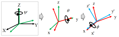
\(\left[ \begin{matrix} \text{X} \\ \text{Y} \\ \text{Z} \\ \end{matrix} \right]=\left[ \begin{matrix} \cos \text{ }\psi & -\sin \text{ }\psi & 0 \\ \sin \text{ }\psi & \cos \text{ }\psi & 0 \\ 0 & 0 & 1 \\ \end{matrix} \right]\left[ \begin{matrix} \cos \text{ }\theta & 0 & \sin \text{ }\theta \\ 0 & 1 & 0 \\ -\sin \text{ }\theta & 0 & \cos \text{ }\theta \\ \end{matrix} \right]\left[ \begin{matrix} 1 & 0 & 0 \\ 0 & \cos \text{ }\phi & -\sin \text{ }\phi \\ 0 & \sin \text{ }\phi & \cos \text{ }\phi \\ \end{matrix} \right]\left[ \begin{matrix} \text{x }\!\!'\!\!\text{ } \\ \text{y }\!\!'\!\!\text{ } \\ \text{z }\!\!'\!\!\text{ } \\ \end{matrix} \right]\)
In line with the sequentially defined rotation order, return rotation angle Ψ on the z-axis, which is the first rotation.
Example
4.7.1.3.1.12. PITCH
The PITCH function returns the rotation angle for the second rotation in a z-y-x sequence of Euler angles.
Format
PITCH(Marker1{, Marker2})
Arguments definition
Marker1 |
The name or argument number of a marker to be calculated |
Marker2 |
|
Formulation
\(\left[ \begin{matrix} \text{X} \\ \text{Y} \\ \text{Z} \\ \end{matrix} \right]=\left[ \begin{matrix} \cos \text{ }\psi & -\sin \text{ }\psi & 0 \\ \sin \text{ }\psi & \cos \text{ }\psi & 0 \\ 0 & 0 & 1 \\ \end{matrix} \right]\left[ \begin{matrix} \cos \text{ }\theta & 0 & \sin \text{ }\theta \\ 0 & 1 & 0 \\ -\sin \text{ }\theta & 0 & \cos \text{ }\theta \\ \end{matrix} \right]\left[ \begin{matrix} 1 & 0 & 0 \\ 0 & \cos \text{ }\phi & -\sin \text{ }\phi \\ 0 & \sin \text{ }\phi & \cos \text{ }\phi \\ \end{matrix} \right]\left[ \begin{matrix} \text{x }\!\!'\!\!\text{ } \\ \text{y }\!\!'\!\!\text{ } \\ \text{z }\!\!'\!\!\text{ } \\ \end{matrix} \right]\)
In line with the sequentially defined rotation order, return rotation angle θ on the y-axis, which is the second rotation.
Example
4.7.1.3.1.13. ROLL
The ROLL function expression calculates the third angle (in radians) of a 3-2-1 Euler rotation sequence between Marker1 and Marker2.
Format
ROLL(Marker1{, Marker2})
Arguments definition
Marker1 |
The name or argument number of a marker to be calculated |
Marker2 |
|
Formulation
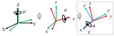
\(\left[ \begin{matrix} \text{X} \\ \text{Y} \\ \text{Z} \\ \end{matrix} \right]=\left[ \begin{matrix} \cos \text{ }\psi & -\sin \text{ }\psi & 0 \\ \sin \text{ }\psi & \cos \text{ }\psi & 0 \\ 0 & 0 & 1 \\ \end{matrix} \right]\left[ \begin{matrix} \cos \text{ }\theta & 0 & \sin \text{ }\theta \\ 0 & 1 & 0 \\ -\sin \text{ }\theta & 0 & \cos \text{ }\theta \\ \end{matrix} \right]\left[ \begin{matrix} 1 & 0 & 0 \\ 0 & \cos \text{ }\phi & -\sin \text{ }\phi \\ 0 & \sin \text{ }\phi & \cos \text{ }\phi \\ \end{matrix} \right]\left[ \begin{matrix} \text{x }\!\!'\!\!\text{ } \\ \text{y }\!\!'\!\!\text{ } \\ \text{z }\!\!'\!\!\text{ } \\ \end{matrix} \right]\)
In line with the sequentially defined rotation order, return rotation angle φ on the x-axis, which is the third rotation.
Example
4.7.1.3.1.14. INCANG
The INCANG function returns the angle in radians between 2 vectors that are made from the positions of either 3 or 4 markers. If the vectors continue to rotate in the same direction past 180 degrees, then the angle returned increases beyond 180 degrees.
(Note: The initial value of INCANG is between 0 and 180, inclusive)
Format
INCANG(Marker1, Marker2{, Marker3}, Marker4)
Arguments definition
Marker1 |
The name or argument number of a marker to be calculated. (the end point of the 1st vector) |
Marker2 |
The name or argument number of a marker to be calculated. (the start point of the 1st vector) |
Marker3 |
|
Marker4 |
The name or argument number of a marker to be calculated. (the end point of the 2nd vector) |
Formulation
\(\begin{aligned} & \text{Angle} \\ & \theta ={{\cos }^{-1}}\left( \frac{{{{\vec{v}}}_{1}}\cdot {{{\vec{v}}}_{2}}}{\left\| {{{\vec{v}}}_{1}} \right\|\left\| {{{\vec{v}}}_{2}} \right\|} \right) \\ & if,\text{ }\left\| {{{\vec{v}}}_{1}} \right\|<1.e-10\text{ }or\text{ }\left\| {{{\vec{v}}}_{2}} \right\|<1.e-10 \\ & \theta ={{\theta }_{saved}}\text{ }\left( innitial\ {{\theta }_{saved}}=0.0 \right) \\ & \\ & \text{Direction} \\ & {{{\vec{v}}}_{3}}={{{\vec{v}}}_{1}}\times {{{\vec{v}}}_{2}} \\ \end{aligned}\)
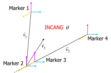
The first value of INCANG is positive angle and the value of INCANG is the cumulative angle on the simulation.
Example
Note
The Scope Expression created from INCANG expression function does not give the result because it cannot be calculated in GUI.