9.7.10. FE Sets and Components
If two or more elements have the same type, then the element component is created automatically.
This is also true of property components.
Sets and components, once created, are selectively displayed using the Display command.
9.7.10.1. Node Set
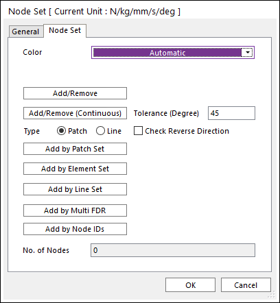
Figure 9.104 Node Set dialog box
Color: Select a color to the node set.
Add/Remove: Select nodes to add or remove for a node set.
Add/Remove (Continuous): Select a patch or line to add or remove continuously with its own patch or line continuity in the angle tolerance for a node set.
Tolerance (Degree): Defines an angle tolerance to check patch or line continuity.
Check Reverse Direction: If this option is checked, nodes are selected regardless to normal direction of patches or lines in the angle tolerance.
Type Patch: Select a patch then continuously connected patches are added, and the nodes of the patches are selected.
Type Line: Select a line then continuously connected lines are added, and the nodes of the lines are selected.
Add by Patch Set: Select a patch set to add to a node set. The node set defines all nodes of the selected patch set.
Add by Element Set: Select an element set to add to a node set. The node set defines all nodes of the selected element set.
Add by Line Set: Select a line set to add to a node set. The node set defines all nodes of the selected line set.
Add by Multi FDR: Select multi FDR element to add to a node set. The node set defines all primary node of the selected FDR element.
Add by Node IDs: Selects nodes to add or remove by Node IDs.
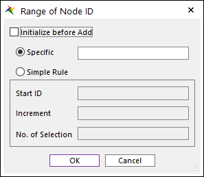
Figure 9.105 Range of Node ID dialog box
Initialize before Add: If this option is checked, initialize selected nodes.
Specific: Selects nodes by specific node ids with “-” and “,”.
Simple Rule: Selects nodes with Start ID, Increment, No. of Selection.
Start ID: Shows the starting node ID.
Increment: Shows the increment of node ID.
No. of Selection: Shows the number of selected node.
No. of Nodes: Show the number of nodes included in the node set.
9.7.10.2. Patch Set
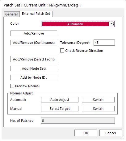
Figure 9.106 Patch Set dialog box
Color: Selects a color to the patch set.
Add/Remove: Selects patches to add or remove for a patch set.
Add/Remove (Continuous): Selects a patch to add or remove for a patch set. RecurDyn/FFlex determines continuity of patches by Tolerance.
Tolerance (Degree): Defines an angle tolerance to check patch continuity.
Check Reverse Direction: If this option is checked, patches are selected regardless to normal direction of patches in the angle tolerance.
Add/Remove (Select Front): Selects patches in front of the view direction to add or remove for a patch set.
Add (Node Set): Selects a node set to add for a patch set. The patch set is defined patches of the selected node set.
Add by Node IDs: Selects nodes to add or remove by Node IDs.
Figure 9.107 Range of Node ID dialog box
Initialize before Add: If this option is checked, initialize selected nodes.
Specific: Selects nodes by specific node ids with “-” and “,”.
Simple Rule: Selects nodes with Start ID, Increment, No. of Selection.
Start ID: Shows the starting node ID.
Increment: Shows the increment of node ID.
No. of Selection: Shows the number of selected node.
Tolerance: Defines the tolerance to determine continuity of patches.
Preview Normal: Previews the normal direction of the patch set.
Normal Adjust: Adjusts the normal direction of the patch set.
Automatic
Auto Adjust: Adjusts the normal direction of the patch set automatically.
Switch: Switches from the normal direction of the patch set to the opposite direction.
Manual
Select Target: Selects the targeted patch set manually.
Switch: Switches from the normal direction of the targeted patch set to the opposite direction.
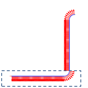
Figure 9.108 Using Select Target in Manual
No. of Patch: Shows the number of patches included in the patch set.
9.7.10.3. Element Set
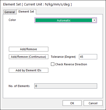
Figure 9.109 Element Set dialog box
Color: Selects a color to the element set.
Add/Remove: Selects elements to add or remove for an element set.
Add/Remove (Continuous): Selects a patch to add or remove continuously with its own patch continuity in the angle tolerance for an element set.
Tolerance (Degree): Defines an angle tolerance to check patch continuity.
Check Reverse Direction: If this option is checked, elements are selected regardless to normal direction of patches in the angle tolerance.
Add by Element IDs: Selects elements to add or remove by Element IDs.
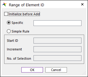
Figure 9.110 Range of Element ID dialog box
Initialize before Add: If this option is checked, initialize selected elements.
Specific: Selects elements by specific element ids with “-” and “,”.
Simple Rule: Selects elements with Start ID, Increment, No. of Selection.
Start ID: Shows the starting element ID.
Increment: Shows the increment of element ID.
No. of Selection: Shows the number of selected element.
No. of Elements: Show the number of elements included in the element set.
9.7.10.4. Line Set
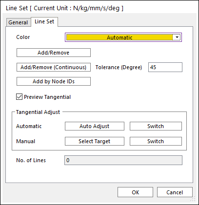
Figure 9.111 Line Set dialog box
Color: Selects a color to the line set.
Add/Remove: Selects lines to add or remove for a line set.
Add/Remove (Continuous): Selects a line to add or remove for a line set. RecurDyn/FFlex determines continuity of lines by Tolerance.
Add by Node IDs: Selects nodes to add or remove by Node IDs.
Figure 9.112 Range of Node ID dialog box
Initialize before Add: If this option is checked, initialize selected nodes.
Specific: Selects nodes by specific node ids with “-” and “,”.
Simple Rule: Selects nodes with Start ID, Increment, No. of Selection.
Start ID: Shows the starting node ID.
Increment: Shows the increment of node ID.
No. of Selection: Shows the number of selected node.
Tolerance: Defines the tolerance to determine continuity of lines.
Preview Tangential: Previews the tangential direction of the line set.
Tangential Adjust: Adjusts the tangential direction of the line set.
Automatic
Auto Adjust: Adjusts the tangential direction of the line set automatically.
Switch: Switches from the tangential direction of the line set to the opposite direction.
Manual
Select Target: Selects the targeted line set manually.
Switch: Switches from the tangential direction of the targeted line set to the opposite direction.
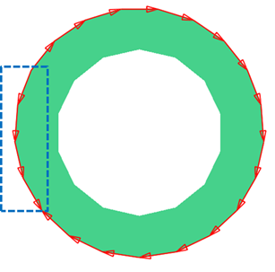
Figure 9.113 Using Select Target in Manual
No. of Line: Shows the number of lines included in the line set.