26.5.2.4. Output
This page can select output nodes.
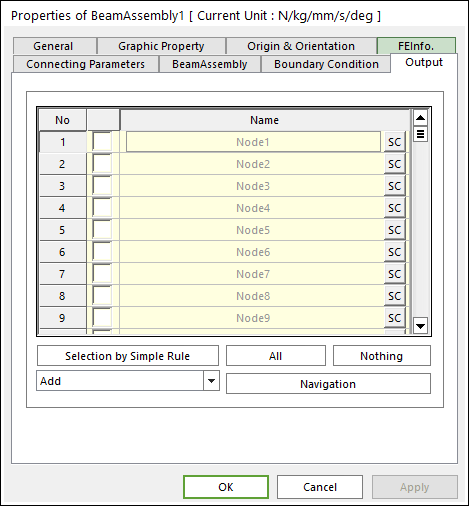
Figure 26.37 Beam Assembly property page [Output page]
Output: The outputs of selected belt bodies are shown in Scope and Plot.
No: Shows the index of belt bodies.
Check Option: If this option is checked, outputs are plotted.
Name: Defines the name of belt bodies belongs to the belt group.
SC: Determines Scope of each belt body. Refer to Scope Entity.
Selection by Simple Rule: Allows the user to open the Selection dialog box to support a simple rule selecting many sheet bodies at the same time.
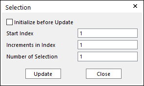
Figure 26.38 Selection dialog box
\(N_{selection}=N_{start}+\Delta*(i-1)\), \(i=1,.....,n\)
Initialize before Update: If this button is checked and click the Update, only the check boxes of sheet bodies selected by user-defined rule are activated. Or not, the check boxes of pre-selected sheet bodies and sheet bodies selected by user-defined rule are activated.
Start Index: Shows the starting index in the simple rule.
Increment in Index: Shows the increment of index in the simple rule.
Number of Selection: Shows the number of selected sheet bodies in the simple rule.
All/Nothing: The check boxes of all belt bodies in the list are activated or deactivated.
Add + Navigation: If the user selects the Add option and clicks the navigation button, the user can select nodes from the screen and an output is applied on the belt bodies.
Remove + Navigation: If the user selects the Remove option and clicks the navigation button, the user can select nodes from the screen and an output is not applied on the belt bodies.
Add or Remove + Navigation: If the user selects the Add or Remove option and clicks the navigation button, the user can select nodes from the screen and a boundary condition is applied or not on the belt bodies.