24.8.2. Arc Guide
The user can define an arc-shaped guide.
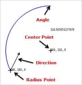
Figure 24.87 Arc Guide
24.8.2.1. Modeling Options
The user can create the arc guide as follows.
Point, Point, Direction, Angle
Point: Selects a point to define the center of the arc guide.
Point: Selects a point to define the starting point on the circumference of the arc guide. The distance between the first point and the second point becomes a radius of the arc guide.
Direction: Defines a direction for revolution of the arc guide.
Angle: Defines a revolution angle of the arc guide.
Point, Point, Direction, Point
Point: Selects a point to define the center of the arc guide.
Point: Selects a point to define the starting point on the circumference of the arc guide. The distance between the first point and the second point becomes a radius of the arc guide.
Direction: Defines a direction for revolution of the arc guide.
Point: Selects a point to define the ending point on the circumference of the arc guide. The point is constrained to be at a constant distance from the center of the arc guide.
GuideMotherBody, Point, Point, Direction, Angle
GuideMotherBody: Selects a body to define the parent body of the arc guide.
Point: Selects a point to define the center of the arc guide.
Point: Selects a point to define the starting point on the circumference of the arc guide. The distance between the first point and the second point becomes a radius of the arc guide.
Direction: Defines a direction for revolution of the arc guide.
Angle: Defines a revolution angle of the arc guide.
Point, Point, Point
Point: Selects a point to define the center of the arc guide.
Point: Selects a point to define the starting point on the circumference of the arc guide. The distance between the first point and the second point becomes a radius of the arc guide.
Point: Selects a point to define the ending point on the circumference of the arc guide.
24.8.2.2. Properties
The properties dialog box of the Arc Guide has three tabs.
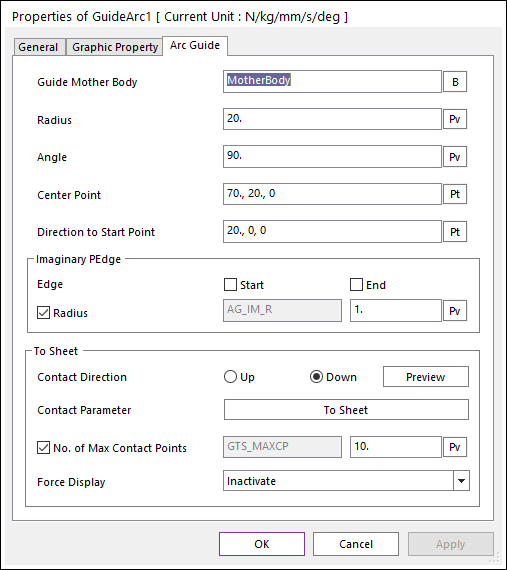
Figure 24.88 Guide Arc property page
Guide Mother Body: Selects the mother body of Arc Guide by clicking B.
Radius: Defines the radius of Arc Guide.
Angle: Defines the angle of Arc Guide.
Center Point: Defines the center point of Arc Guide.
Direction to Start Point: Defines the direction to the start point of Arc Guide.
Imaginary PEdge: Defines an imaginary PEdge on start and/or end point of Arc Guide. The imaginary PEdge is a circle shape and located start/end point. And the center point of imaginary PEdge is located negative direction of contact (normal) direction. User can see the imaginary PEdge by clicking Preview.
Edge: Defines Enable(Checked) or Disable(Unchecked) on the Start and/or End point.
Radius: Defines a radius of the imaginary PEdge. The user can set a connection with SPV value.
Contact Direction: Allows seeing the direction of contact with the sheet on the arc guide by clicking Preview. If the direction is not correct the user can switch between Up and Down.
Contact Parameter: Allows the user to modify contact parameters by clicking To Sheet. In this dialog box, the user can modify the contact parameters of contact forces applied between the sheet and the guide. Refer to Contact formulas for MTT2D.
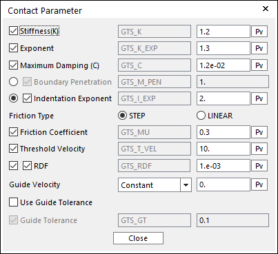
Figure 24.89 Contact Parameter dialog box
No. of Max Contact Points: Defines the number of max contact point for output. User can define this value from 1 to 5000. This value only affects Force Display and RPLT data about the contact points. The default value is 10.
Force Display: Graphically displays the all contact force vectors (the sum of the normal and tangential contact force) at each contact point up to the No. of Max Contact Point.
Note
The angular tolerance of arc guide is radian unit.