30.2.7. Silent Chain Link
A pair of silent chain link consists of an outer link and inner link. A user must create a pair of chain link from which all chain links are copied. Once a pair of chain links is created, it is registered as clone body. The inertial properties of the assembled chain link are automatically duplicated as the values of clone body. A single pin is used to connect two links of a chain system in this model. The geometric information provided by a user is used for both display and contact force computation in the solver. Therefore, the chain link properties must be defined carefully prior to assembling a chain system.
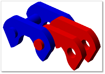
Figure 30.47 Silent Chain link geometry
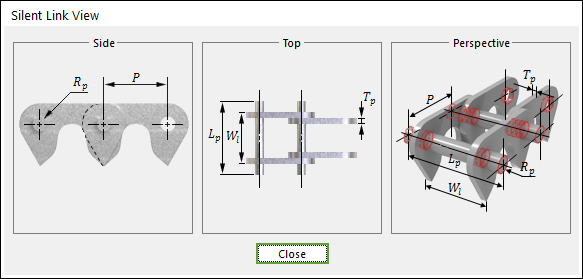
Figure 30.48 Silent Chain link dimension information
P |
Pitch |
Wl |
Total Width of Outer Link |
Tp |
Plate Thickness |
Rp |
Pin Radius |
Lp |
Pin Length |
30.2.7.1. Modeling Options
The user can create a chain link as follows.
Point, WithDialog
Point: Selects a point on Ground to define the chain link. It doesn’t matter where the chain link is because the created body is a clone body for segment assembly.
WithDialog: Modifies the property for the chain link. The chain link is created with clicking OK.
30.2.7.2. Properties
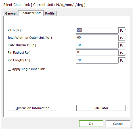
Figure 30.49 Silent Chain Link property page [Characteristics page]
The Silent Chain Link property page is shown in Figure 30.49. The parameters are explained below. In order to understand the geometry, refer to Dimension Information.
Pitch (P): Enters the pitch.
Total Width of Outer Link (Wl): Enters the width between outer link plates.
Plate Thickness (Tp): Enters the thickness of link plate.
Pin Radius (Rp): Enters the pin radius of link.
Pin Length (Lp): Enters the pin length of link.
Apply single Inner Link: it is possible to create the following geometry.
Use User-defined Bushing Position: If it is checked, Bushing force can be defined on different position with pin position.
Left Bushing Position: Defines a base marker position of Bushing force.
Right Bushing Position: Defines an action marker position of Bushing force.
Bushing Width: Defines a width between two bushing forces.
All data is same to Roller Chain Link. For more information, click here.
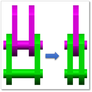
Figure 30.50 Single Inner Link and Double Inner Link
Dimension Information: Shows dimension information of the geometry for Roller Link.
Calculator: It is useful for finding specific value to define the relation of between sprockets and chain links. Refer to Calculator.
30.2.7.2.1. Profile
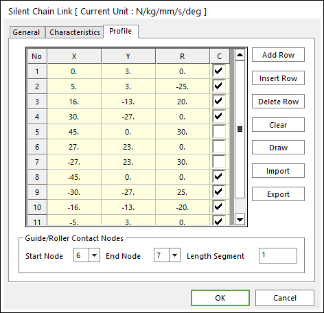
Figure 30.51 Silent Chain Link property page [Profile page]
X,Y,R: Points and radius.
C: Determines whether to use points for contact.
Add Row: Adds a row to the end of the table.
Insert Row: Inserts a row where the cursor is and move the current and later rows down.
Delete Row: Deletes the row where the cursor is and move the later rows up.
Clear: Deletes all rows in the table.
Draw: All data must be defined with respect to the link marker. You can move points graphically by using the mouse directly.
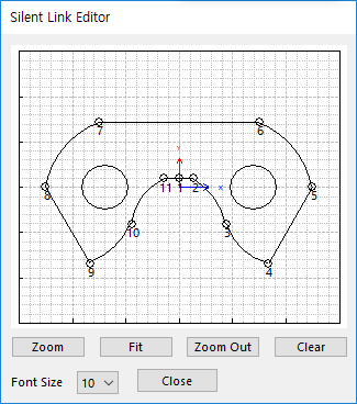
Figure 30.52 Silent Link Editor dialog box
Import: Imports the X, Y, and R data pairs from a CSV file or a MAT file or a text file. In the case of the text file, the usage of the comma, the tab, and the space can be the delimiter between the three columns in the file. And when using the Excel file, the user can select the Tab-delimited text file output option or the CSV (Comma-Separated Values) file output option to save the Excel file which can be imported.
Export: Exports the X, Y, and R data pairs to a CSV file or a MAT file or a text file.
Guide/Roller Contact Nodes: Defines a contact region of the link for contact with Guide or Roller entities.
Start Node: Selects a start node to define the contact region of the link.
End Node: Selects an end node to define the contact region of the link.
Length Segment: The contact region from Start Node to End Node is a line and meshed with this value.
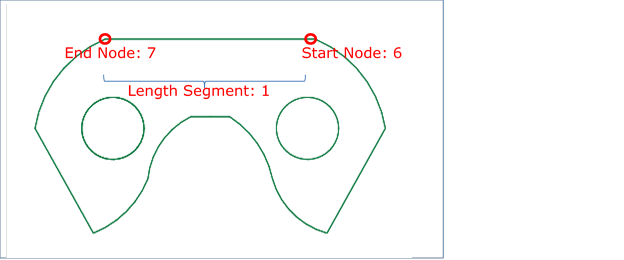
Figure 30.53 Definition of Guide/Roller Contact Nodes