6.4.2.6. Solid
A Solid Contact generates a force between one solid (or available surface for a solid contact) and the other solid (or available surface for a solid contact).
Two solid geometries must belong to two different bodies. And user also uses an available surface instead of solid geometry. But when the user uses a surface instead of solid geometry, the contacted volume must be enclosed during the whole solving time as shown Figure 6.339.
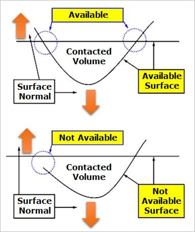
Figure 6.339 Definition of an available surface for a Solid Contact
The contact force can be not only linear or exponential but also nonlinear spline characteristics to the contact penetration and its velocity.
The base solid (or available surface) or action solid (or available surface) can be approximated as multi triangular patches with the Patch option as shown in Figure 6.340.
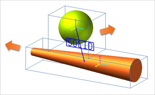
Figure 6.340 Approximated action and base contact solids
6.4.2.6.1. Modeling Options
In the case of Solid contact, solid, shell, and surface geometry types are supported without base and action geometries when creating.
Solid(Shell), Solid(Shell)
Solid(Shell): Selects a solid or a shell to define a base solid.
Solid(Shell): Selects a solid or a shell to define an action solid.
Solid(Shell), MultiSolid(Shell)
Solid(Shell): Selects a solid or a shell to define a base solid.
MultiSolid(Shell): Selects some solids or shells to define action solids.
Solid(Shell), Solid(Shell), Solid(Shell), Solid(Shell)
Solid(Shell): Selects a solid or a shell to define a base solid.
Solid(Shell): Selects a solid or a shell to define an action solid.
Solid(Shell): Selects a solid or a shell to define another base solid.
Solid(Shell): Selects a solid or a shell to define another action solid.
MultiSolid(Shell), MultiSolid(Shell)
MultiSolid(Shell): Selects some solids or shells to define base solids.
MultiSolid(Shell): Selects some solids or shells to define action solids.
Surface, Surface
Surface: Selects a surface to define a base solid.
Surface: Selects a surface to define an action solid.
Surface, MultiSurface
Surface: Selects a surface to define a base solid.
MultiSurface: Selects some surfaces to define action solids.
Surface, Surface, Surface, Surface
Surface: Selects a surface to define a base solid.
Surface: Selects a surface to define an action solid.
Surface: Selects a surface to define another base solid.
Surface: Selects a surface to define another action solid.
MultiSurface, MultiSurface
MultiSurface: Selects some surfaces to define base solids.
MultiSurface: Selects some surfaces to define action solids.
Solid(Shell), Surface
Solid(Shell): Selects a solid or a shell to define a base solid.
Surface: Selects a surface to define an action solid.
Surface, Solid(Shell)
Surface: Selects a surface to define a base solid.
Solid(Shell): Selects a solid or a shell to define an action solid.
6.4.2.6.2. Properties
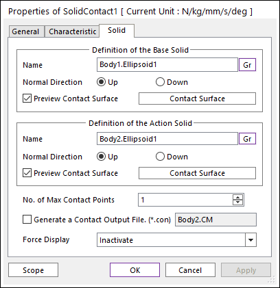
Figure 6.341 Properties of Solid dialog box
Entity Name: Defines the name of base solid (or available surface). The base solid (or available surface) can be dispatched from the Working Window by clicking Gr.
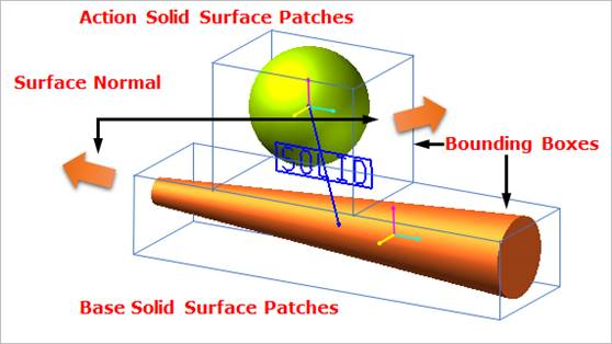
Figure 6.342 Preview of the normal directions, contact patches and nodes
Preview Contact Surface: If this option is checked, the patches making the contact surface are shown on the Working Window as shown in the above figure.
Contact Surface: Accesses the Solid Patch dialog box as shown in the below figure.
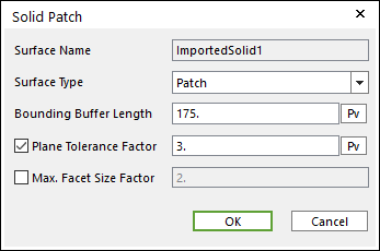
Figure 6.343 Solid Patch dialog box
Surface Type: Select only the Patch type for a contact surface. In the Patch type, the contact surface is approximated to multiple triangular patches.
Bounding Buffer Length: Before calculating the collision detection, contact pre-search are performed with base and action bounding box. The bounding buffer length defines the offset length of bounding box compared to the real bounding box as shown in Figure 6.344.
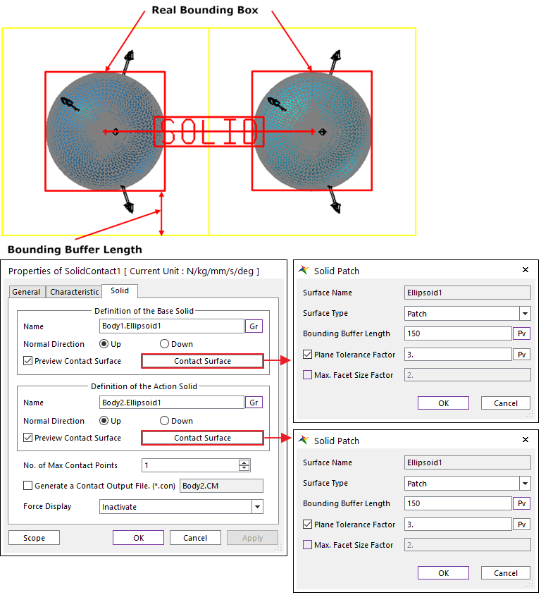
Figure 6.344 Definition of Bounding Buffer Length
Plane Tolerance Factor: Specifies the surface tolerance factor as a value from 0 to 10. A smaller value produces a more refined patch. For more information, click here.
Max. Facet Size Factor: Specifies the max. facet size factor as a value from 0 to 10. This value controls the maximum size of triangular patch length. Even though box geometry, if this value is defined (checked), box geometry can be used with lots of triangular patches as shown in Figure 6.345.
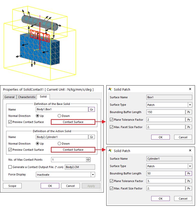
Figure 6.345 Example of Plane Tolerance Factor and Max. Facet Size Factor
No. of Max Contact Point: Defines the number of max contact point.
Generate the contact output file(*.con): When user checks the Generate the contact output file option, RecurDyn creates the contact output file based on the contact output reference marker which can be defined in the contact force page. The user can calculate the local contact information based on the contact output reference by using *.con output file’. Then Recurdyn/Solver reports all contact-related information to the text file. The format is as follows:
Col.
Variables
Descriptions
1
Time
Simulation Time
2
NCP
Total number of calculated contact points
3
NO
Current contact point number
4
X_RefPos
Position X of Output Reference Marker from Global
5
Y_RefPos
Position Y of Output Reference Marker from Global
6
Z_RefPos
Position Z of Output Reference Marker from Global
7
Z_EulerA
Z Euler Angle of Output Reference Marker from Global
8
X_EulerA
X Euler Angle of Output Reference Marker from Global
9
Z_EulerA
Z Euler Angle of Output Reference Marker from Global
10
X_ConPos
Position X of Calculated Contact Reference Frame from Global
11
Y_ConPos
Position Y of Calculated Contact Reference Frame from Global
12
Z_ConPos
Position Z of Calculated Contact Reference Frame from Global
13
X_NorDir
Normal Direction X of Calculated Contact Reference Frame from Global
14
Y_NorDir
Normal Direction Y of Calculated Contact Reference Frame from Global
15
Z_NorDir
Normal Direction Z of Calculated Contact Reference Frame from Global
16
X_TanDir
Tangent(Friction) Direction X of Calculated Contact Reference Frame from Global
17
Y_TanDir
Tangent(Friction) Direction Y of Calculated Contact Reference Frame from Global
18
Z_TanDir
Tangent(Friction) Direction Z of Calculated Contact Reference Frame from Global
19
Pen
Penetration Depth
20
PenVel
Penetration Depth Velocity or Relative Velocity in Normal Direction
21
TanVel
Relative Velocity in Tangent Direction
22
FricCoeff
Friction Coefficient
23
NorForce
Normal Force Magnitude
24
FricForce
Friction Force Magnitude
Force Display: Graphically displays the resultant force vector on the view window.