40.1.2. Properties
The user can modify the property using the MMS Type A property page.
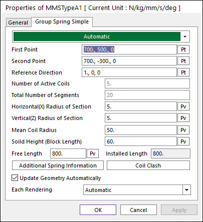
Figure 40.6 MMS Type A property page
First Point: Defines the clicked point primary. The button part of spring is defined on this point.
Second Point: Defines the clicked point secondary. The top part of spring is defined on this point. The installed length of spring is the distance between the first point and the second point.
Reference Direction: Indicates the Geometric Starting point of MMS Type A. Please refer to below Figure 40.7.
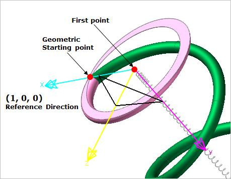
Figure 40.7 Reference Direction
Number of Active Coils: Defines the active part of spring. MMS Type A consists of active part and inactive parts (upper and lower end body block). Refer to below Figure 40.8 and the explanation about the solid height (Block length). After fixing this parameter, you cannot modify this value again.
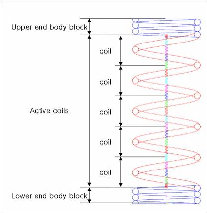
Figure 40.8 Number of Active coils
Total Number of segments: Enter the number of segments of active coil part of spring. After fixing this parameter, the user cannot modify this value again.
Horizontal (x) Radius of Section: Enter the Horizontal Radius of Section.
Vertical (z) Radius of section: Enter the horizontal Radius of Section.
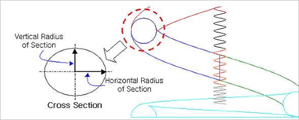
Figure 40.9 Horizontal / Vertical Radius of Section
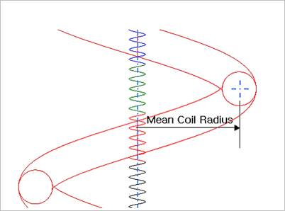
Figure 40.10 Mean Coil Radius
Solid Height (Block length) is the length when the spring is compressed fully. The formulation is as follow.
\({{L}_{block\_height}} \ge 2{{r}_{z}}\left( 1+{{n}_{act\_coil}} \right)\)
\({{r}_{z}}\) = vertical radius of section\({{n}_{act\_coil}}\) = number of active coils\({{L}_{block\_height}}\) = Solid Height (Block Height)- \({{L}_{upper\_end\_block}}={{L}_{lower\_end\_block}}=\left( {{L}_{block\_height}}-2{{r}_{z}}{{n}_{act\_coil}} \right)/2\)
- \({{L}_{upper\_end\_block}}\) = Upper end body block length\({{L}_{lower\_end\_block}}\) = Lower end body block length
Free Length: Enter the free length value
Install length: Shows the installed length of MMS Type A.
Additional Spring Information
Coil Clash: The parameters are used to represent coil clash as arguments of the IMPACT function.
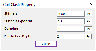
Figure 40.11 Coil Clash Property dialog box
Update Geometry Automatically: If this option is unchecked, the position and orientation of the geometry constituting the group are not updated depending on variables in the property page. So, after executing Extract function, this option is unchecked.
Each Rendering: The selected mode can be displayed in Each Render mode.