34.2.6. Push Rod
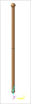
Figure 34.130 Push Rod
34.2.6.1. Properties
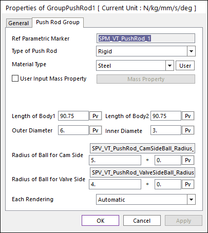
Figure 34.131 Push Rod property page
Ref Parametric Marker: Controls the position of Push Rod. It is also special parametric marker (SPM).
Type of Push Rod: Selects the type of Push Rod. It defines the connection method between multi bodies.
Material Type: Selects a material type. Three method are supported. For more information, click here.
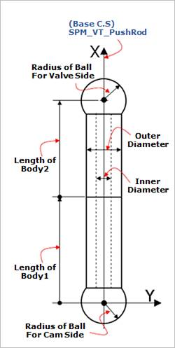
Figure 34.132 Geometric Information
Length of Body1: Defines a length of Body1 for Push Rod.
Length of Body2: Defines a length of Body2 for Push Rod.
Outer Diameter: Defines an outer diameter of Push Rod.
Inner Diameter: Defines an inner diameter of Push Rod.
Radius of Ball for Cam Side: Defines a radius of ball for Cam Side.
Radius of Ball for Valve Side: Defines a radius of ball for Valve Side.
Each Rendering: The selected mode can be displayed in Each Render mode.
34.2.6.1.1. Type of Push Rod
Rigid Type
All multi bodies are connected by fixed joint. It acts like one body.
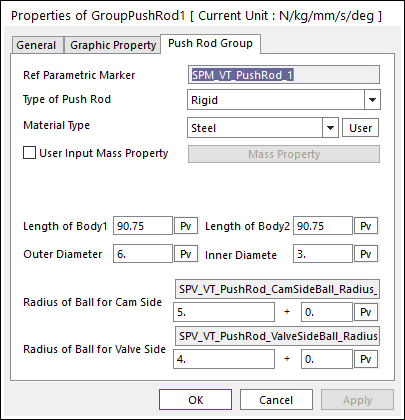
Figure 34.133 Push Rod property page [Rigid Type]
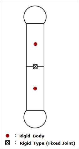
Figure 34.134 Rigid Type of the Push Rod
Beam Type
Multi bodies are connected by Beam Force. It acts like flexible body.
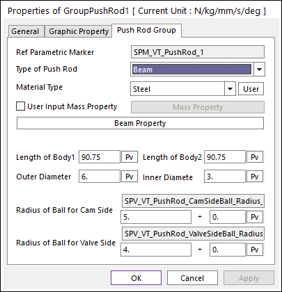
Figure 34.135 Push Rod property page [Beam Type]
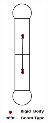
Figure 34.136 Beam Type of the Push Rod
The user can modify the property of Beam Force that connects multi bodies. The user has to specify the value of Shear Modulus that is used to calculate Beam Force. For more information, refer to Beam Force.
If the user clicks Beam Property, the user can see the following dialog box.
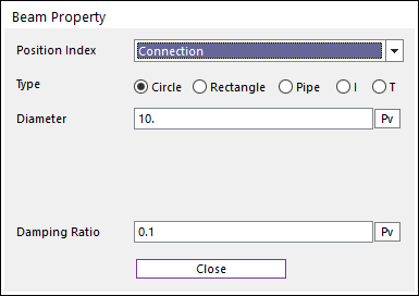
Figure 34.137 Beam Property dialog box