24.8.1. Guide Body
If the user needs to include an arc guide and a linear guide in a certain body, the user can create a guide body using this tool.
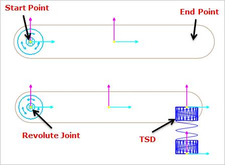
Figure 24.83 Guide Body
The created Guide Body has no contact information defined internally. This is useful when used as the mother body of other guide entities as the below figure.
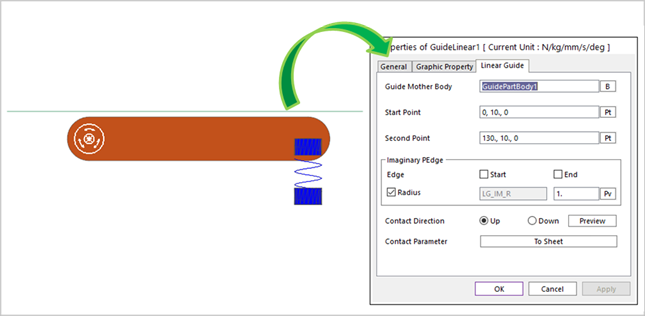
Figure 24.84 Example to use Guide Body
24.8.1.1. Modeling Options
The user can create the guide body as follows.
Point, Point
Point: Selects a point to define a start point of the guide body.
Point: Selects a point to define a second point of the guide body.
Point, Point, Radius
Point: Selects a point to define a start point of the guide body.
Point: Selects a point to define a second point of the guide body.
Radius: Defines a radius of the guide body.
24.8.1.2. Properties
The properties dialog box of the Guide Body Group has two tabs.
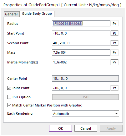
Figure 24.85 Guide Body property page
Radius: Defines the radius of guide body.
Start Point: Defines the start point of guide body.
Second Point: Defines the end point of guide body.
Mass: Defines the mass of guide body.
Inertia Moment (Izz): Defines the mass Moment of Inertia with respect to the z-axis of the center marker.
Center Point: Is the position of the center of the mass marker.
Joint Point: Defines the position of revolute joint.
TSD Option: If the user checks this option, the user can be active Translational Spring Damper (TSD) force. The user can modify TSD properties by clicking TSD.
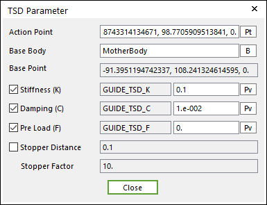
Figure 24.86 TSD Parameter dialog box
Action Point: Defines the position of action marker of TSD force applied on the action body.
Base Body: Defines the name of base body.
Base Point: Defines the position of base marker of the TSD force applied on the base body.
Stiffness (K): Defines the stiffness coefficient of the TSD.
Damping(C): Defines the damping coefficient of the TSD.
PreLoad (F): Defines the pre-Load applied to the TSD.
Stopper Distance, Stopper Factor: Refer to Guide Entities.
Each Rendering: The selected mode can be displayed in Each Render mode.