27.3.2.4. Bushing Force
In practice, the single pin track link system of a low mobility tracked vehicle is modeled as a series of bodies connected by bushings around the link pins which are inserted into a shoe body with a radial pressure to reduce rattling of the pin. The bushings tend to reduce the high impulsive contact forces by providing cushion and reducing the relative angle between the track links. In this bushing force, a continuous force model is used to represent the pin connections. This force model is a non-linear function of the coordinates of the two links.
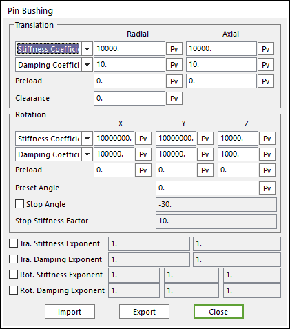
Figure 27.62 Pin Bushing dialog box
The Pin Bushing is a radial type bushing. For more information, click here.
Clearance
When rubber bushings wear out, the connections get clearance in the radial direction. In such a case, there are no longer like perfect bushings. The user is able to model the bushings with gap by using the clearance.
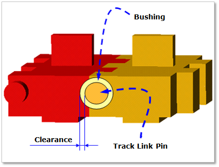
Figure 27.63 Clearance
Preset Angle
Bushings are intentionally bended initially to prevent a too large rotational deformation of the bushings when they pass around the sprocket or idler. For example, if the rotation of one link relative to its adjacent link is 14 degrees while passing around the sprocket, the pin bushing rotates only 7 degrees if the initial preset angle is 7 degrees instead of 14. As a result, the pin bushing experiences only torque equivalent to the 7 degrees of deformation. This increases the life cycle of the rubber bushing pin.
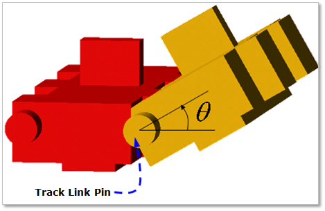
Figure 27.64 Preset Angle
Stop Angle
Two adjacent grousers often come in contact. So, the relative rotation of two grousers is limited. This rotational limitation can be modeled by a stop angle. The stop angle can be defined by checking in Stop angle and Stop stiffness factor in the pin bushing dialog box. Therefore, Bending back about z-axis direction is prevented by Stop angle. Stop angle is modeled by multiplying stiffness coefficient by Stop stiffness factor when the rotational angle of Z-axis passes over the stop angle
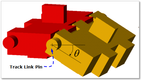
Figure 27.65 Stop angle
27.3.2.4.1. Bushing force model for single pin track
In the bushing force model for single pin track, a compliant force model is used to define the pin joint connections. This force model is a non-linear function of the coordinates of the two links. In order to define the generalized compliant bushing forces, several coordinate systems are introduced. Two centroidal body coordinate systems for the track links i and j, a joint coordinate systems origin is assumed to be located at the geometric center of the circular groove containing the pin and the bushing for track link i, and a pin coordinate system for track link j whose origin is rigidly attached to the center of the pin. Note that because of the bushing effect, the origins of the joint and pin coordinate systems do not always coincide. The displacement of the pin coordinate system with respect to the joint coordinate system is a function of the bushing stiffness. Also note that the location and orientation of the joint coordinate system can be determined as a function of the generalized coordinates of link i. For simplicity, it is assumed in this bushing force model that the location and orientation of the pin coordinate system can be defined in terms of the coordinates of link j. The radial spring provides the restoring force due to the combined translational deformation of the rubber bushings on XY plane direction as shown in Figure 27.66. The axial spring restricts the translational motion of the two links along the lateral direction as shown in Figure 27.66. The rotational springs are used to model the relative rotational deformation between the two track links.
The magnitude of the force produced by the radial spring is
\({F}^{j}_{r} =-K_{Rr} \delta_{r}-C_{Rr} \dot{\delta}_r\)
where, \(K_{Rr}\) is the spring stiffness coefficient, and \(C_{Rr}\) is the damping coefficient. Similarly, the restoring force due to the translational spring along the Z axis is
\({F}^{j}_{z} =-K_{Rz} \delta_{z}-C_{Rz} \dot{\delta}_z\)
where, \(\delta_{z}\) is translational deformation of the pin coordinate systems of body j with respect to the pin coordinate systems of body i along the Z axis, \(K_{Rz}\) and \(C_{Rz}\) are the stiffness and damping coefficients. The torque as the result of the relative rotation of link j with respect to link i are given by
\({T}^{j}_{\theta} =-K_{\theta} \theta - C_{\theta} \theta\)
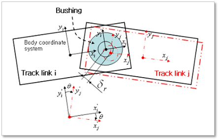
Figure 27.66 Bushing force model for single pin link