24.12. Specialized Outputs
RecurDyn/MTT2D automates the generation of relevant outputs for a sheet feeding system, saving the user valuable time converting the general outputs into data needed to design or analyze his system. The following table summarizes the custom outputs for RecurDyn/MTT2D.
Group |
Plot Content |
Outputs |
|
Sheet |
FM_Contact FX_Tangential FY_Normal TZ_Contact |
Contact Forces in the Tangent and Normal Directions to Center of Mass Marker (CM) |
|
_Nodal |
Generalized nodal forces at the center position of a segmented sheet body. If there is no nodal force in the body, the result is zero. The force is measured in the reference frame of sheet body (or nodal). |
||
_Air_Resistance |
Air Resistance Forces. If the Air Resistance Coefficient option is not checked, the result is zero. The force is measured in the reference frame of sheet body (or nodal). |
||
Impulse |
Impulse of Contact Forces |
||
Fixed Roller/FE Fixed Roller |
MeanSlip_SHT |
Slip and Mean Value of the Difference of Tangential Velocities between Roller and Contacted Sheet Bodies |
|
FrictionF_SHT NormalF_SHT |
Contact Forces in the Tangent and Normal Direction at Contact Point |
||
ContactFM_SHT ContactFX_SHT ContactFY_SHT ContactTZ_SHT |
Generalized Forces and Torque from Contact Forces between Fixed Roller and Sheet. The force vector is defined acting on CM of the Fixed Roller. Reference frame is CM of the Mother body of the MTT2D subsystem. |
||
Impulse_DT |
Impulse of a driving or driven torque |
||
Att ackAngle_SHT_HEAD Att ackAngle_SHT_TAIL |
Attack Angle (Degree) |
||
ContactPoints |
The contact points data are written sorted by the bigger normal force. Each contact point data are 15 values includes contact position vector, normal direction vector, friction direction vector, penetration depth, penetration velocity, tangential relative velocity, friction coefficient, normal force, and friction force. The number of outputs is defined as the No. of Max Contact Point on the Contact page of the properties dialog. |
||
Movable Roller/FE Movable Roller |
To Sheet Contact |
MeanSlip_SHT |
Slip and Mean Value of the Difference of Tangential Velocities between Roller and Contacted Sheet Bodies |
FrictionF_SHT NormalF_SHT |
Contact Forces in the Tangent and Normal Direction at Contact Point |
||
ContactFM_SHT ContactFX_SHT ContactFY_SHT ContactTZ_SHT |
Generalized Forces and Torque from Contact Forces between Movable Roller and Sheet. The force vector is defined acting on CM of the Movable Roller. Reference frame is CM of the Mother body of the MTT2D subsystem. |
||
Att ackAngle_SHT_HEAD Att ackAngle_SHT_TAIL |
Attack Angle (Degree) |
||
To Roller Contact |
MeanSlip_FR |
Slip and Difference of Tangential Velocities between Roller and Fixed Roller |
|
FrictionF_FR NormalF_FR |
Contact Forces in the Tangent and Normal Direction at Contact Point |
||
ContactFM_FR ContactFX_FR ContactFY_FR ContactTZ_FR |
Generalized Forces and Torque from Contact Forces between Movable Roller and Fixed Roller. The force vector is defined acting on CM of the Movable Roller. Reference frame is the CM of the Movable Roller. |
||
To Other Contacts |
SoftNip_NF |
Contact Normal Force for Soft Nip |
|
MaxGap_NF |
Contact Normal Force for Maximum Gap |
||
Contact Points |
ContactPoints_SHT ContactPoints_FR |
The contact points data are written sorted by the bigger normal force. Each contact point data are 15 values includes contact position vector, normal direction vector, friction direction vector, penetration depth, penetration velocity, tangential relative velocity, friction coefficient, normal force, and friction force. The number of outputs is defined as the No. of Max Contact Point on the Contact page of the properties dialog. |
|
Movable Roller |
Impulse_DT |
Impulse of a driving or driven torque |
|
Guides |
MeanSlip_SHT |
Slip and Mean Value of Difference of Tangential Velocities between Guide and Contacted Sheet Bodies |
|
FrictionF_SHT NormalF_SHT |
Contact Forces in the Tangent and Normal Direction at Contact Point |
||
ContactFM_SHT ContactFX_SHT ContactFY_SHT ContactTZ_SHT |
Generalized Forces and Torque from Contact Forces between Guide and Sheet. The force vector is defined acting on joint position of the Guide mother body. Reference frame is the CM of the Guide mother body. |
||
Att ackAngle_SHT_HEAD Att ackAngle_SHT_TAIL |
Attack angle |
||
ContactPoints |
The contact points data are written sorted by the bigger normal force. Each contact point data are 15 values includes contact position vector, normal direction vector, friction direction vector, penetration depth, penetration velocity, tangential relative velocity, friction coefficient, normal force, and friction force. The number of outputs is defined as the No. of Max Contact Point on the Contact page of the properties dialog. |
||
Sensor |
Speed Sensor |
Value |
Speed of the Sheet passing by the Sensor in a defined direction |
Event Sensor |
Value |
When a head or tail of Sheet is passing by the Sensor, the result is 1, or not 0. Also, users can use the event time. |
|
Distance Sensor |
Value |
Minimum Distance of the Sheet from Sensor in a defined direction |
Attack Angle (Degree)
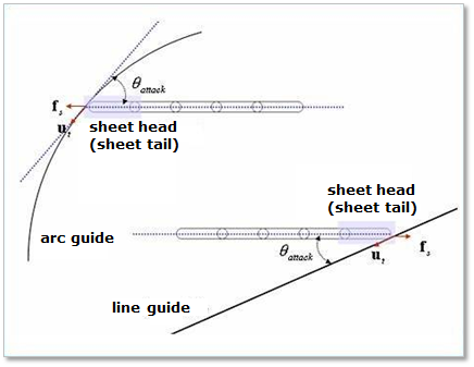
Figure 24.105 Attack Angle
The user can measure an attack angle when a head or a tail of sheet is contacted with a linear guide, arc guide, fixed roller, or movable roller as shown in Figure 24.105. (In the case of fixed and movable roller are similar the arc guide case in Figure 24.105.) If two sheet-heads or two sheet-tails are contacted with a guide, the attack angle of later contacted sheet is reported. The value of attack angle is always reported in the degree unit and less than 90 degree. The value of attack angle can be calculated from the following equation.
\(f_s\cdot u_t=f_s^Tu_t=|f_s||u_t|\cos\theta\)
\((|f_s|=|u_t|=1)\)
\(\theta=\cos^{-1}(f_s^Tu_t)\)
\(\theta > \frac{\pi}{2} \Rightarrow \theta = \pi - \theta\)
In the FE fixed roller or FE movable roller case, Attack angle is defined as Figure 24.106. If the deformation is small of the FE roller, then the computing result is similar to the attack angle of the rigid roller.
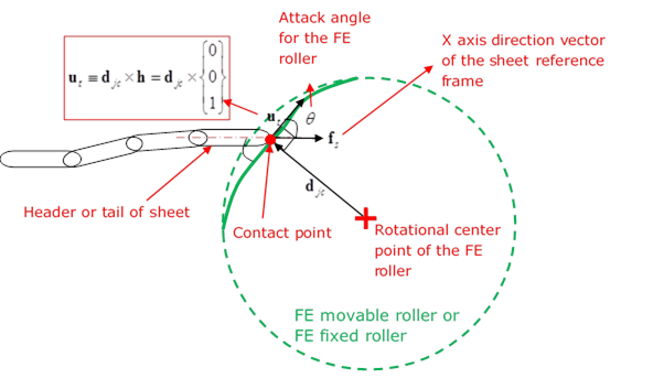
Figure 24.106 Attack Angle for the FE Fixed/Movable Roller