6.3.3.5. Buoyancy
A Buoyancy force is the upward force exerted by a fluid on an object that is partially or completely submerged in the fluid. The magnitude of the buoyant force depends on the density of the fluid and the volume of the object submerged in the fluid. According to Archimedes’ principle, the buoyant force is equal to the weight of the fluid displaced by the object.
6.3.3.5.1. Modeling Options
The user can create a force entity as follows.
Marker, Surface(PatchSet)
Marker: Selects a marker. This marker defines a reference of fluid surfcae of buoyant force.
Surface(PatchSet): Selects a surface or a patch set of Flexible Body to define a target body.
Marker, Solid(PatchSet)
Marker: Selects a marker. This marker defines a reference of fluid surfcae of buoyant force.
Solid(PatchSet): Selects a solid or a patch set of Flexible Body to define a target body.
Marker, MultiSurface(PatchSet)
Marker: Selects a marker. This marker defines a reference of fluid surfcae of buoyant force.
MultiSurface(PatchSet): Selects some surfaces or patch sets of Flexible Body to define a target body
Marker, MultiSolid(PatchSet)
Marker: Selects a marker. This marker defines a reference of fluid surfcae of buoyant force.
MultiSolid(PatchSet): Selects some solids or patch sets of Flexible Body to define a target body.
6.3.3.5.2. Properties
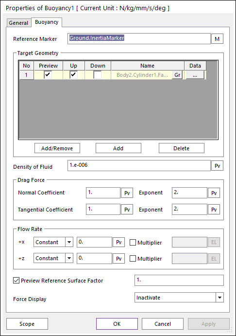
Figure 6.285 Buoyancy Force property page
The buoyancy force and drag force are calculated as following.
\(\overrightarrow{F}_{Buoyancy}=-\rho V g \overrightarrow{u_{n}}\)
\(\overrightarrow{F}_{NormalDrag}=-0.5C_{d}\rho A (\overrightarrow{\upsilon}_{relative}\cdot\overrightarrow{u}_{d} )^{e_{d}} \overrightarrow{u_{d}}\)
\(\overrightarrow{F}_{TangentialDrag}=-C_{t}\rho A (\overrightarrow{\upsilon}_{relative}\cdot\overrightarrow{u}_{t} )^{e_{t}} \overrightarrow{u_{t}}\)
Where, the inputs into the equation are defined in the following table:
\(\overrightarrow{F}_{Buoyancy}\) |
Buyancy Force |
|
\(\rho\) |
Density of fluid |
|
\(V\) |
Volume |
Submerged volume of target geometries. |
\(g\) |
Gravity Magnitude |
Magnituce value of Gravity. |
\(\overrightarrow{u_{n}}\) |
Direction vector of buoyancy force |
In general, this direction vector is same as Y-direction of reference marker. |
\(\overrightarrow{F}_{NormalDrag}\) |
Normal Drag Force |
|
\(A\) |
Area |
Area of geometry(face surface). |
\(C_{d}\) |
Coefficient of Normal Drag Force |
Default value is 1. |
\(e_{d}\) |
Normal Drag force Exponent |
Default value is 2. |
\(\overrightarrow{\upsilon}_{relative}\) |
Relative Velocity |
\(\overrightarrow{\upsilon}_{relative} = \overrightarrow{\upsilon}_{geomety}-\overrightarrow{\upsilon}_{flow}\) |
\(\overrightarrow{u_{d}}\) |
Direction vector of Normal Drag force |
This direction vector is same as geometry normal direction. |
\(C_{t}\) |
Coefficient of Tangential Drag Force |
Default value is 1. |
\(e_{t}\) |
Tangential Drag force Exponent |
Default value is 2. |
\(\overrightarrow{u_{t}}\) |
Direction vector of Tangential Drag force |
\(\overrightarrow{u}_{t} = \frac{\overrightarrow{\upsilon}_{relative}}{\left| \overrightarrow{\upsilon}_{relative} \right|}-\overrightarrow{u}_{d}\) |
Reference Marker |
Marker to determine fluid’s Surface. |
Target Geomety |
The geometry list to be used to calculate buoyancy force. |
Density of Fluid |
The value of density of fluid. The unit of this value is the system of units defined by Dialog. |
Drag Force ( Normal & Tangential ) |
Define the drag force coefficient and Exponent for each direction. |
Flow Rate ( +x & +z ) |
Define the flow rate and multiplier for each direction. The directions +x and +z are same as reference marker’s +x and +z. There are 2 method to define flow rate, ‘Constant’ and ‘Spline’. The multiplier can be defined using expression. |
Preview Reference Surface Factor: Diplay the surface of fluid.
Force Display: Displays the resultant force vector graphically on Working Window.
6.3.3.5.3. Calculation
Flow Rate ( \(\overrightarrow{\upsilon}_{flow}\) )
There are 2 directions to define the flow Rate. Do not consider the Y-direction of reference marker. This Y-directions is same as depth direction. Even if the depth is changed, the flow rates are same.
To define the flow rate there are 2 methods of each direction.
Constant : Set same value for velocity of fluid.
Spline : Set spline values for Velocity of fluid.
In addition, there are 2 multipliers for each direction. These multipliers can be operated switch(on/off) and multiplier.
The flow rate equation is :
\(\overrightarrow{\upsilon}_{flow, x} = {C}_{x}{T}_{x}\overrightarrow{u}_{x}\)
\(\overrightarrow{\upsilon}_{flow, z} = {C}_{z}{T}_{z}\overrightarrow{u}_{z}\)
\(\overrightarrow{\upsilon}_{flow} = \overrightarrow{\upsilon}_{flow, x} +\overrightarrow{\upsilon}_{flow, z}\)
\({C}_{x}\) |
Flow Rate value of x direction |
\({C}_{z}\) |
Flow Rate value of z direction |
\({T}_{x}\) |
Multiplier value of x direction |
\({T}_{z}\) |
Multiplier value of z direction |
\(\overrightarrow{u}_{x}\) |
x direction of reference marker |
\(\overrightarrow{u}_{z}\) |
z direction of reference marker |
Note
The x value of spline is not time but position. The y value of spline is velocity.
Submerged Volume
\(V_{p}=-(\overrightarrow{n_{p}}\cdot\overrightarrow{g})d_{up/down}A_{p}h\)
\(V_{submerged}=\sum_{}^{}V_{p}\)
\(\overrightarrow{V_{p}}\) |
Volume of patch |
|
\(\overrightarrow{n_{p}}\) |
Patch Normal Direction |
|
\(\overrightarrow{g}\) |
Gravity |
Submerged volume of target geometries. |
\(d_{up/down}\) |
Up/Down Direction value |
Up = 1. Down = -1. This value can be control in Bouyancy properties windows. |
\(A_{p}\) |
Area of patch |
|
\(h\) |
Normal Drag Force |
Height. Distance from patch center to fluid surface. |
Warning
The submerged volume can be negative value on RPLT when the target geometries are surfaces.