4.12.1. Examples for General Constraints
The user can use a general constraint as follows:
Spherical Joint
To make the spherical joint, create the any body.
Create a marker in the ground.
Create a marker in the body at the same position of a marker of ground.
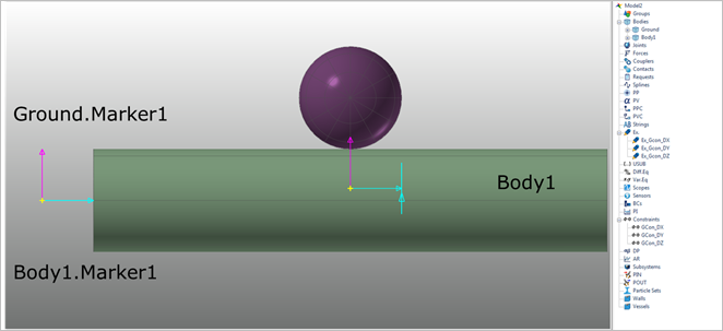
Figure 4.154 Create body and marker
Make three general constraint expression for constraint 3 translation DOF.
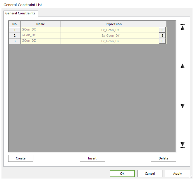
Figure 4.155 General Constraint List dialog box
Gcon_DX, Gcon_DY, Gcon_DZ mean distances of Ground.Marker1 and Body1.Marker1 each axis of Body1.Marker1 are ZERO.
General Constraint Expression.
DX(Ground.Marker1,Body1.Marker1) = ZERO
DY(Ground.Marker1,Body1.Marker1) = ZERO
DZ(Ground.Marker1,Body1.Marker1) = ZERO
Distance Joint
To make the distance joint, create the any body.
Create a marker in the ground.
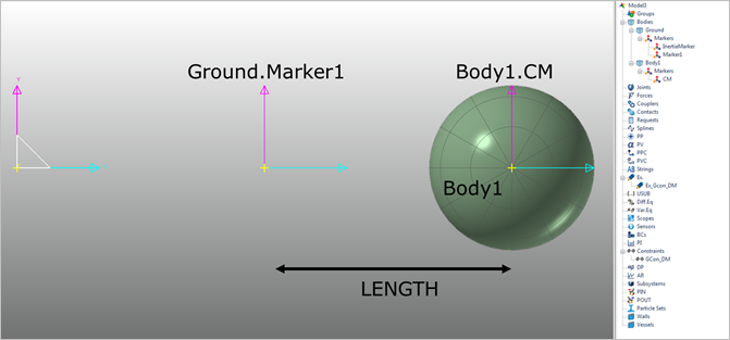
Figure 4.156 Create body and marker
Make a general constraint expression for constraint same distance.
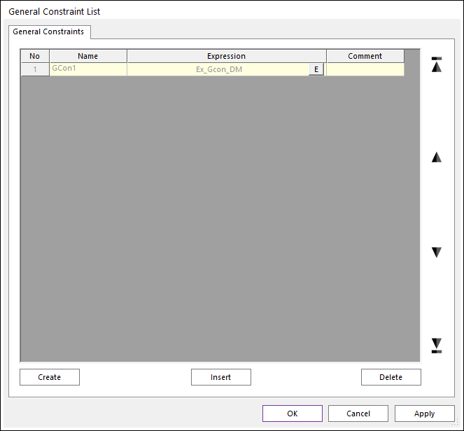
Figure 4.157 General Constraint List dialog box
Gcon_DM mean distances of Body1.CM and Ground.Marker1 each axis of Ground.Marker1 minus LENGTH are ZERO.
General Constraint Expression.
DM(Body1.CM,Ground.Marker1) - LENGTH = ZERO
Caution
The LENGTH is not be ZERO in using DM expression.
DM(1,2) = ZERO is not define the direction of reaction force. So the simulation is stopped.
Revolute Joint
To make the revolute joint, create the any body.
Create two markers in the ground for the vector equation.
These two markers represent the Z vector of base body.
Create three markers in the body for the vector equation.
These three markers represent each X and Y vector of action body.
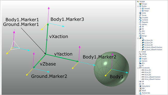
Figure 4.158 Create body and marker
Make five general constraint expression for constraint 3 translation and 2 rotation DOF.
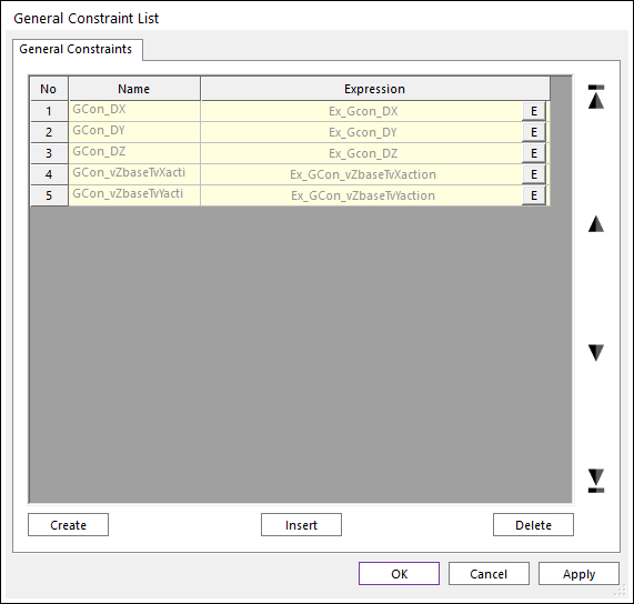
Figure 4.159 General Constraint List
These general constraint equations mean base marker and action marker are same position and only Z vector direction of base is free.
General Constraint Expression.
DX(Body1.Marker1,Ground.Marker1) = ZERO
DY(Body1.Marker1,Ground.Marker1) = ZERO
DZ(Body1.Marker1,Ground.Marker1) = ZERO
DX(Ground.Marker2,Ground.Marker1)*DX(Body1.Marker2,Body1.Marker1) + DY(Ground.Marker2,Ground.Marker1)*DY(Body1.Marker2,Body1.Marker1) + DZ(Ground.Marker2,Ground.Marker1)*DZ(Body1.Marker2,Body1.Marker1) = ZERO
DX(Ground.Marker2,Ground.Marker1)*DX(Body1.Marker3,Body1.Marker1) + DY(Ground.Marker2,Ground.Marker1)*DY(Body1.Marker3,Body1.Marker1) + DZ(Ground.Marker2,Ground.Marker1)*DZ(Body1.Marker3,Body1.Marker1) = ZERO
Wire System
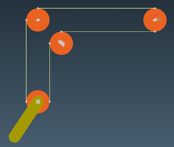
Figure 4.160 Example model
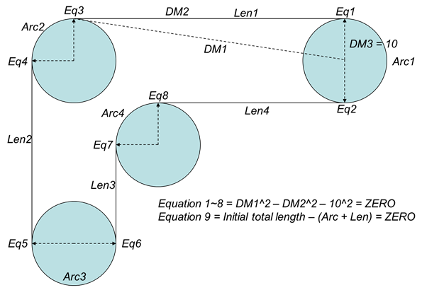
Figure 4.161 Mathematical equations of the example model