5.5.2.2. Step to Execute FRA
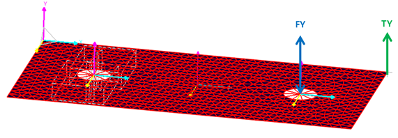
Figure 5.40 Example mode for FRA
Prepare a Model.
Define the input and output by selecting markers in the Excitation Loads for RFlex and/or Rigid Body.
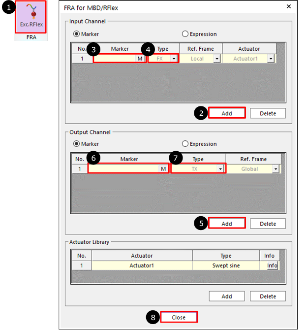
Figure 5.41 Definition of FRA Excitation Loads
Click the Exc.RFlex icon of the FRA group in the Flexible tab.
Click Add in Input Channel group.
Click M and then select a marker for input.
Select the Type as FX, FY, FZ, TX, TY and TZ.
Click Add in Output Channel group
Click M and then select a marker for output.
Select the Type as TX, TY, TZ, RX(Roll), RY(Pitch), RZ(Yaw), VX, VY, VZ, WX, WY, WZ, ACCX, ACCY, ACCZ, WDTX, WDTY, WDTZ, TM, VM, WM, ACCM, and WDTM.
Click OK.
Set Start /End Frequency and Step.
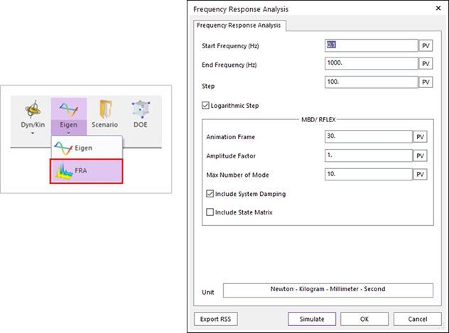
Figure 5.42 Definition of Frequency Response Analysis
Draw the result.
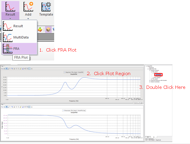
Figure 5.43 Drawing FRA Plot