9.9.8. FCurve To FCurve Contact

The FCurve To FCurve Contact generates a contact force between FFlex bodies.

  • The Patch Set must be defined before creating the contact.

  • The contact surfaces must belong to FFlex body.

  • Two contact surfaces should be two different patch sets.

  • The contact force is generated with the compliance characteristics allowing to the penetration.

The action and base contact surfaces are approximated as multi cylinder and sphere in the line and node of the beam element as shown in Figure 9.137.

../_images/image2122.png

Figure 9.137 Contact geometry

Contact points

  • The lines of action cylinders are examined whether they are contacted with the lines of base cylinders.

  • And then, the action spheres are examined whether they are contacted with the base cylinders.

  • Finally, the base spheres are examined whether they are contacted with the action cylinders.

9.9.8.1. Modeling Options

  • Patch Set, Patch Set

  • Patch Set, Multi Patch Set

  • Patch Set, Patch Set, Patch Set, Patch Set

  • Multi Patch Set, Multi Patch Set

9.9.8.2. Properties

../_images/image2142.png

Figure 9.138 FCurveToFCurve property page

  • Entity Name: Defines the name of base patch set. The base patch set is dispatched from the screen by clicking Gr.

  • Preview Contact Surface: If this option is checked, the patches making the contact surface are highlighted on the screen.

  • Contact Curve: Accessing Contact Curve dialog box as shown in Figure 9.139.

    ../_images/image2111.png

    Figure 9.139 Flexible Curve dialog box

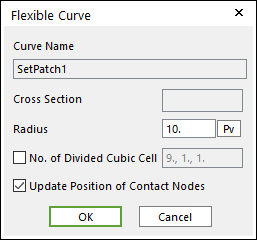
    • Cross Section: The cross section of beam patch set. The cross section is a circle.

    • Radius: The radius of circle. The radius of cylinder and sphere of the contact geometry is determined by this value.

    • No. of Divided Cubic Cell: The number of cubic cells dividing a contact boundary box. This value is automatically calculated. But if need be, the value can be modified by user.

    • Update Position of Contact Nodes: A flag whether the position of nodes belong to the patch set is updated during a simulation. If your system is the small deformation problem and this option is off, the solving time can be improved.

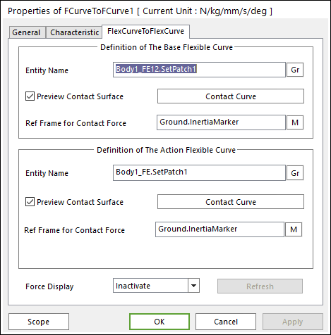
  • Ref. Frame for Contact Surface: The contact force applied on the action body is reported as a force generalized on the defined marker. If the marker is not defined, the default is Ground.Inertia Marker.

  • Force Display: Graphically displays the resultant force vector on the view window.

  • Refresh: When the action or base contact patch set is changed, you can refresh the preview of information of specified contact patch set as using this function.